• Home
  • Download PDF
  • Order CD-ROM
  • Order in Print
Figure 3. Sensor Inspection.
Figure 5. Pedal Assembly Cover.

Maintenance Manual For Motorized Road Grader Model 120M - 5 Page Navigation
  150    151    152    153    154  155  156    157    158    159    160  
img
.
TM 5-3805-293-23-5
0288
INSTALLATION
000288
N OT E
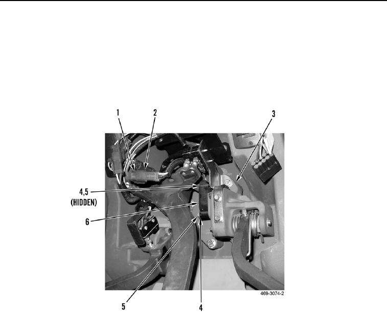
Install wires as noted during removal.
1. Install throttle position sensor (Figure 4, Item 6), two washers (Figure 4, Item 4), and bolts (Figure 4, Item 5) on
pedal assembly (Figure 4, Item 3).
2. Connect electrical connector (Figure 4, Item 2) to lower cab harness (Figure 4, Item 1).
Figure 4. Position Sensor.
0288
0288-5


Privacy Statement
Press Release
Contact

© Copyright Integrated Publishing, Inc.. All Rights Reserved.