
TM 5-3805-293-23-4
0269
REMOVAL CONTINUED
000269
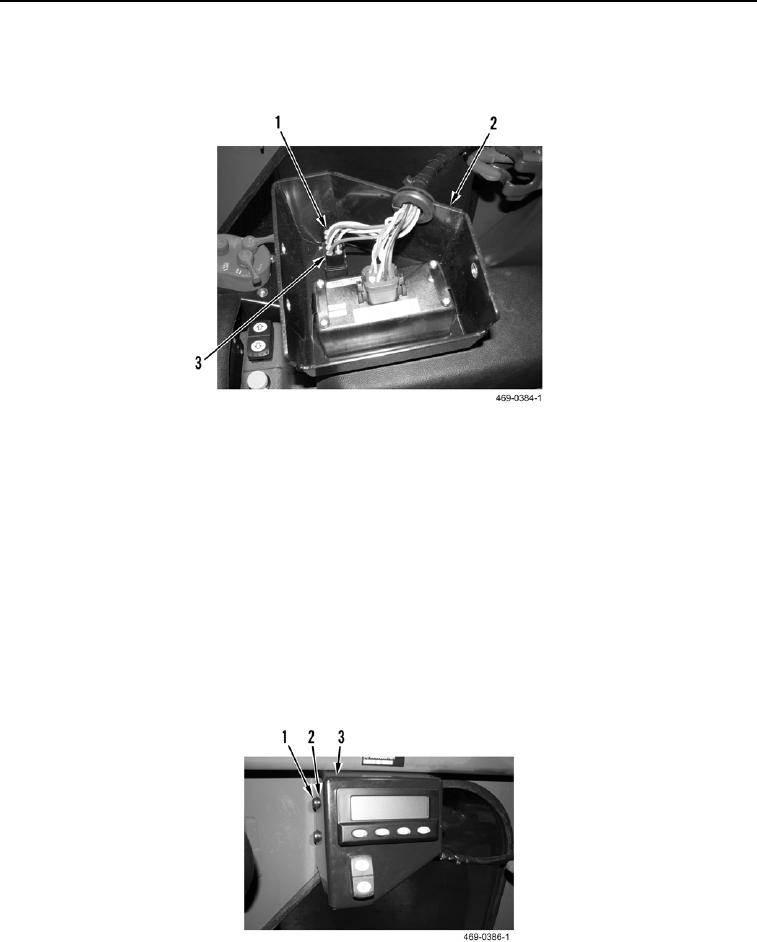
2. Disconnect harness connector (Figure 2, Item 1) from implement lockout switch (Figure 2, Item 3).
3. Remove implement lockout switch (Figure 2, Item 3) from messenger housing (Figure 2, Item 2).
Figure 2. Implement Lockout Switch.
0269
END OF TASK
CLEANING AND INSPECTION
000269
Clean and inspect all electrical parts IAW Electrical General Maintenance Instructions (WP 0347).
END OF TASK
INSTALLATION
000269
1. Install implement lockout switch (Figure 2, Item 1) on messenger housing (Figure 2, Item 1).
2. Connect harness connector (Figure 2, Item 1) to implement lockout switch (Figure 2, Item 1).
3. Install messenger housing (Figure 3, Item 3), three washers (Figure 3, Item 2), and screws (Figure 3, Item 1)
on cab.
Figure 3. Messenger Housing.
0269
END OF TASK

