
TM 5-3805-293-23-4
0265
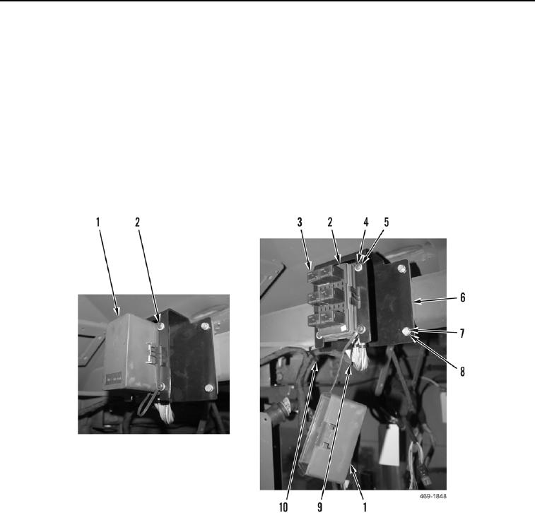
REMOVAL CONTINUED
14. Remove cover (Figure 6, Item 1) from relay panel (Figure 6, Item 2).
N OT E
Mark the location of relays to aid in installation.
15. Remove six relays (Figure 6, Item 3) from relay panel (Figure 6, Item 2).
16. Remove four screws (Figure 6, Item 4), washers (Figure 6, Item 5), cover (Figure 6, Item 1) and relay panel
(Figure 6, Item 2) from bracket (Figure 6, Item 6).
17. Remove tiedown strap (Figure 6, Item 10) from cab upper wiring harness (Figure 6, Item 9). Discard tiedown
strap.
18. Remove four bolts (Figure 6, Item 7), washers (Figure 6, Item 8) and bracket (Figure 6, Item 6) from cab.
Figure 6. Relay Panel Connections.
0265

