
TM 5-3805-293-23-4
0253
REMOVAL CONTINUED
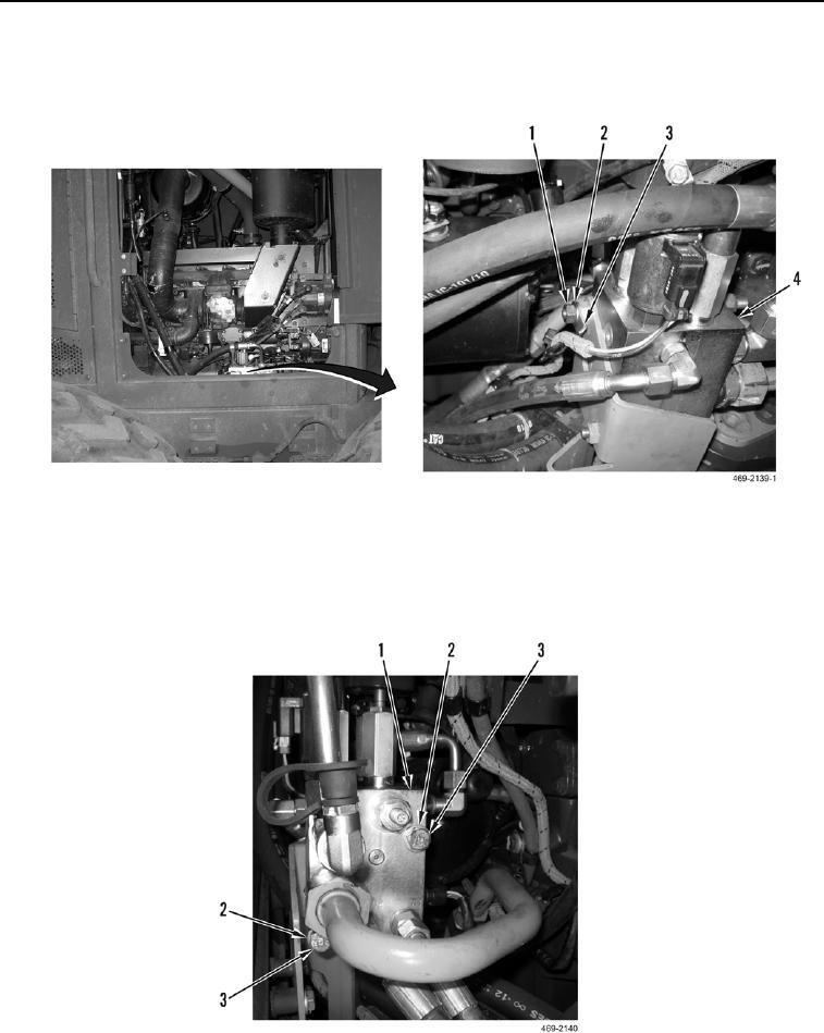
7. Remove nut (Figure 4, Item 1), washer (Figure 4, Item 2), and clip (Figure 4, Item 3) from hydraulic brake and
fan manifold (Figure 4, Item 4).
Figure 4. Wiring Harness Clip.
0253
8. Remove two bolts (Figure 5, Item 2) and washers (Figure 5, Item 3) from hydraulic brake and fan manifold
(Figure 5, Item 1).
9. Position hydraulic brake and fan manifold (Figure 5, Item 1) aside.
Figure 5. Hydraulic Brake and Fan Manifold.
0253

