
TM 5-3805-293-23-4
0204
INSTALLATION
000204
N OT E
Route wiring harness on machine as noted during removal.
Assistance will be requiredduring this procedure.
1. Position wiring harness (Figure 3, Item 4) on machine.
2. Install two eyelets (Figure 3, Item 5) and bolt (Figure 3, Item 6) on frame (Figure 3, Item 7).
3. Connect blackout light wiring harness connector (Figure 3, Item 2) to bulkhead (Figure 3, Item 1).
4. Install tiedown strap (Figure 3, Item 3) on blackout light wiring harness (Figure 3, Item 4).
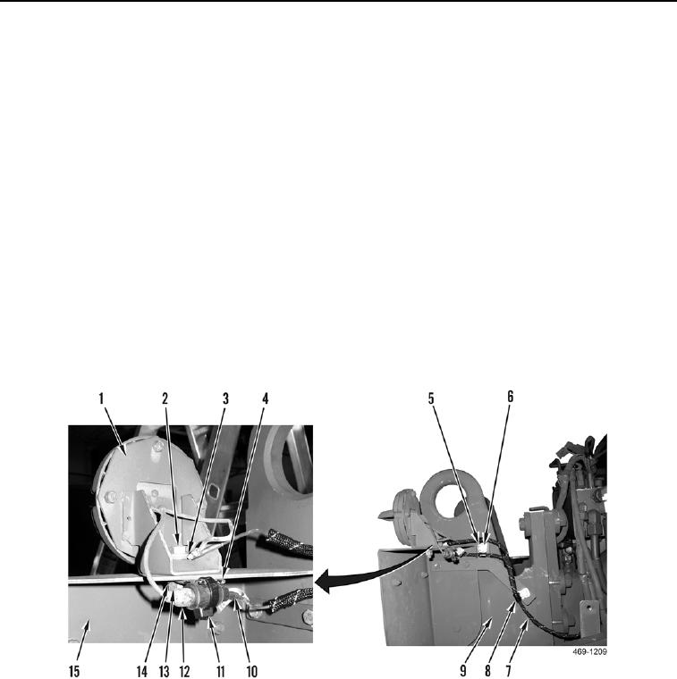
5. Install three clamps (Figure 4, Item 8) on blackout light wiring harness (Figure 4, Item 6).
6. Install three clamps (Figure 4, Item 8), washers (Figure 4, Item 6) and bolts (Figure 4, Item 5) on frame (Figure
4, Item 9).
7. Install blackout lamp (Figure 4, Item 1), bolt (Figure 4, Item 2), clip (Figure 4, Item 4), two eyelets (Figure 4,
Item 3), washers (Figure 4, Item 14), and nut (Figure 4, Item 13) on bracket (Figure 4, Item 15).
8. Connect blackout light wiring harness connector (Figure 4, Item 10) to blackout light connector (Figure 4,
Item 12).
9. Install new tiedown strap (Figure 4, Item 11) on blackout light wiring harness connector (Figure 4, Item 10).
Figure 4. Blackout Light Connection.
0204

