
TM 5-3805-293-23-4
0199
INSTALLATION CONTINUED
N OT E
Install hoses and inserts as noted during removal.
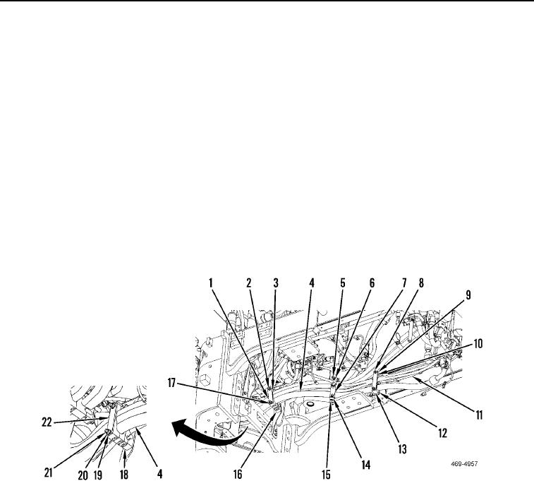
5. Reposition inserts (Figure 9, Item 13) and wire/hose bundles (Figure 9, Item 4) and filter bypass, pump drive
solenoid harness (Figure 9, Item 11). Install plate (Figure 9, Item 10), two washers (Figure 9, Item 9), and lock-
nuts (Figure 9, Item 8) on studs (Figure 9, Item 12) and wire/hose bundles (Figure 9, Item 4).
6. Reposition inserts (Figure 9, Item 15), wire/hose bundles (Figure 9, Item 4) and filter bypass, pump drive sole-
noid harness (Figure 9, Item 11). Install plate (Figure 9, Item 7), two washers (Figure 9, Item 6), and locknuts
(Figure 9, Item 5) on studs (Figure 9, Item 14) and wire/hose bundles (Figure 9, Item 4).
7. Reposition inserts (Figure 9, Item 16), wire/hose bundles (Figure 9, Item 4) and filter bypass, pump drive sole-
noid harness (Figure 9, Item 11). Install plate (Figure 9, Item 1), two washers (Figure 9, Item 3), and locknuts
(Figure 9, Item 2) on studs (Figure 9, Item 17) and wire/hose bundles (Figure 9, Item 4).
8. Reposition inserts (Figure 9, Item 18), wire/hose bundles (Figure 9, Item 4) and filter bypass, pump drive sole-
noid harness (Figure 9, Item 11). Install plate (Figure 9, Item 22), two washers (Figure 9, Item 19), and locknuts
(Figure 9, Item 20) on studs (Figure 9, Item 21) and wire/hose bundles (Figure 9, Item 4).
Figure 9. Filter Bypass and Pump Drive Solenoid Harness.
0199

