
TM 5-3805-293-23-4
0199
REMOVAL CONTINUED
N OT E
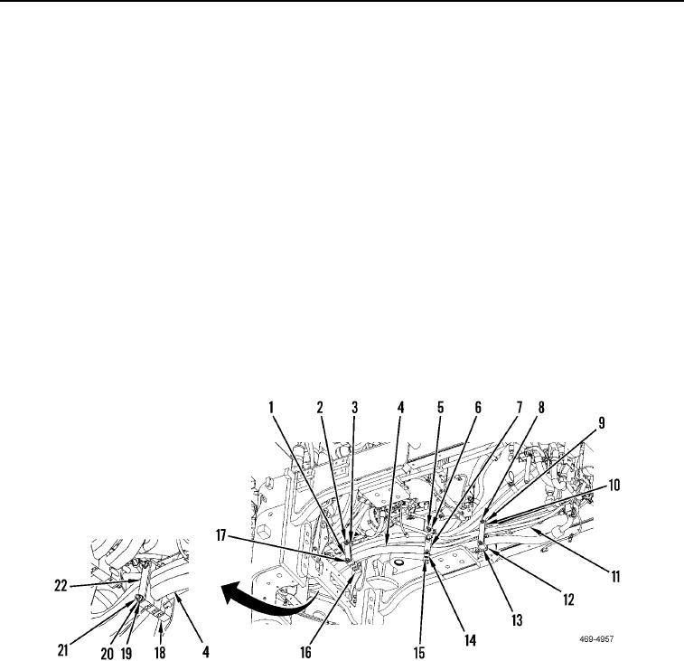
Note position of hoses and inserts prior to removal to aid in installation.
7. Remove two locknuts (Figure 6, Item 20), washers (Figure 6, Item 19), and plate (Figure 6, Item 22) from studs
(Figure 6, Item 21) and wire/hose bundles (Figure 6, Item 4). Separate inserts (Figure 6, Item 18), wire/hose
bundles (Figure 6, Item 4) and filter bypass, pump drive solenoid harness (Figure 6, Item 11). Discard locknuts.
8. Remove two locknuts (Figure 6, Item 2), washers (Figure 6, Item 3), and plate (Figure 6, Item 1), from studs
(Figure 6, Item 17) and wire/hose bundles (Figure 6, Item 4). Separate inserts (Figure 6, Item 16) and wire/
hose bundles (Figure 6, Item 4) and filter bypass, pump drive solenoid harness (Figure 6, Item 11). Discard
locknuts.
9. Remove two locknuts (Figure 6, Item 5), washers (Figure 6, Item 6), and plate (Figure 6, Item 7) from studs
(Figure 6, Item 14) and wire/hose bundles (Figure 6, Item 4). Separate inserts (Figure 6, Item 15) and wire/
hose bundles (Figure 6, Item 4) and filter bypass, pump drive solenoid harness (Figure 6, Item 11). Discard
locknuts.
10. Remove two locknuts (Figure 6, Item 8), washers (Figure 6, Item 9), and plate (Figure 6, Item 10) from studs
(Figure 6, Item 12) and wire/hose bundles (Figure 6, Item 4). Separate inserts (Figure 6, Item 13) and wire/
hose bundles (Figure 6, Item 4) and filter bypass, pump drive solenoid harness (Figure 6, Item 11). Discard
locknuts.
Figure 6. Filter Bypass and Pump Drive Solenoid Harness.
0199

