
TM 5-3805-293-23-4
0190
REMOVAL CONTINUED
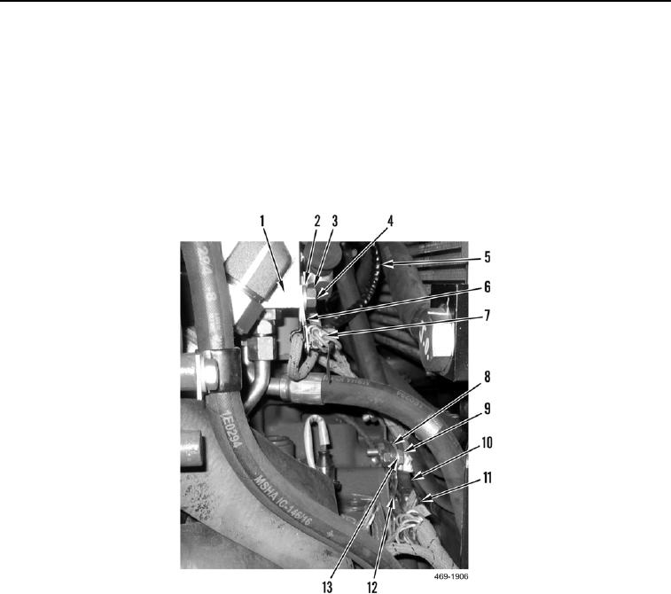
5. Remove bolt (Figure 3, Item 4), nut (Figure 3, Item 3), washer (Figure 3, Item 2), and two clips (Figure 3,
Item 6) from implement steering control manifold (Figure 3, Item 1).
6. Disconnect hydraulic valve wiring harness connector (Figure 3, Item 7) from pressure sensor pigtail (Figure 3,
Item 5).
7. Remove bolt (Figure 3, Item 9), washer (Figure 3, Item 13), and harness clip (Figure 3, Item 12) from bracket
(Figure 3, Item 8).
8. Disconnect hydraulic valve wiring harness connector (Figure 3, Item 10) from main rear wiring harness con-
nector (Figure 3, Item 11).
Figure 3. Hydraulic Valve Wiring Harness.
0190
END OF TASK
CLEANING AND INSPECTION
000190
1. Clean and inspect all mechanical components IAW Mechanical General Maintenance Instructions (WP 0346).
2. Clean and inspect all electrical components IAW Electrical General Maintenance Instructions (WP 0347).
END OF TASK

