
TM 5-3805-293-23-4
0187
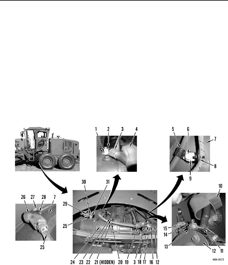
INSTALLATION CONTINUED
3. Route cable (Figure 8, Item 25) on machine. Install cable, washer (Figure 8, Item 28), and bolt (Figure 8,
Item 27), and reposition boot (Figure 8, Item 26) on frame (Figure 8, Item 7).
4. Install cable (Figure 8, Item 25), washer (Figure 8, Item 31), and nut (Figure 8, Item 30) and reposition boot
(Figure 8, Item 29) on secondary steering pump (Figure 8, Item 24).
5. Route cable (Figure 8, Item 3) on machine.
6. Install bolt (Figure 8, Item 23), clip (Figure 8, Item 20), two washers (Figure 8, Item 22), and nut (Figure 8,
Item 21) on secondary steering pump (Figure 8, Item 24).
7. Install cable (Figure 8, Item 3), washer (Figure 8, Item 1), and nut (Figure 8, Item 2), and reposition boot
(Figure 8, Item 4) on secondary steering pump (Figure 8, Item 22).
8. Install new lockwasher (Figure 8, Item 18), cable (Figure 8, Item 3), washer (Figure 8, Item 17), and nut
(Figure 8, Item 16), and reposition boot (Figure 8, Item 19) on secondary steering relay (Figure 8, Item 12).
9. Route cable (Figure 8, Item 11) on machine.
10. Install new lockwasher (Figure 8, Item 14), cable, washer (Figure 8, Item 13), and nut (Figure 4, Item 15), and
reposition boot (Figure 8, Item 10) on secondary steering relay (Figure 8, Item 12).
11. Install clamp (Figure 8, Item 5), clip (Figure 8, Item 8), washer (Figure 8, Item 9), and bolt (Figure 8, Item 6) on
frame (Figure 8, Item 7).
Figure 8. Secondary Steering Pump.
0187

