
TM 5-3805-293-23-4
0180
INSTALLATION CONTINUED
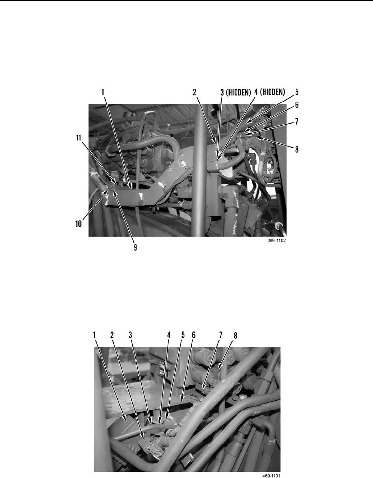
6. Install bracket (Figure 12, Item 8), spacer (Figure 12, Item 11), washer (Figure 12, Item 10), and bolt
(Figure 12, Item 9) on machine.
7. Install clip (Figure 12, Item 5), washer (Figure 12, Item 7), and bolt (Figure 12, Item 6) to bracket (Figure 12,
Item 8).
8. Install clip (Figure 12, Item 2), washer (Figure 12, Item 3), and nut (Figure 12, Item 4) to bracket (Figure 12,
Item 1).
Figure 12. Front Attachment Harness Clips.
0180
9. Install two clips (Figure 13, Item 5), washers (Figure 13, Item 4), and bolts (Figure 13, Item 3) on bracket
(Figure 13, Item 6).
10. Connect six front attachment harness connectors (Figure 13, Item 7) to rear frame valve bank (Figure 13,
Item 8).
11. Connect front attachment harness connector (Figure 13, Item 2) to steering control valve (Figure 13, Item 1).
Figure 13. Rear Frame Valve Bank Connections.
0180

