
TM 5-3805-293-23-4
0175
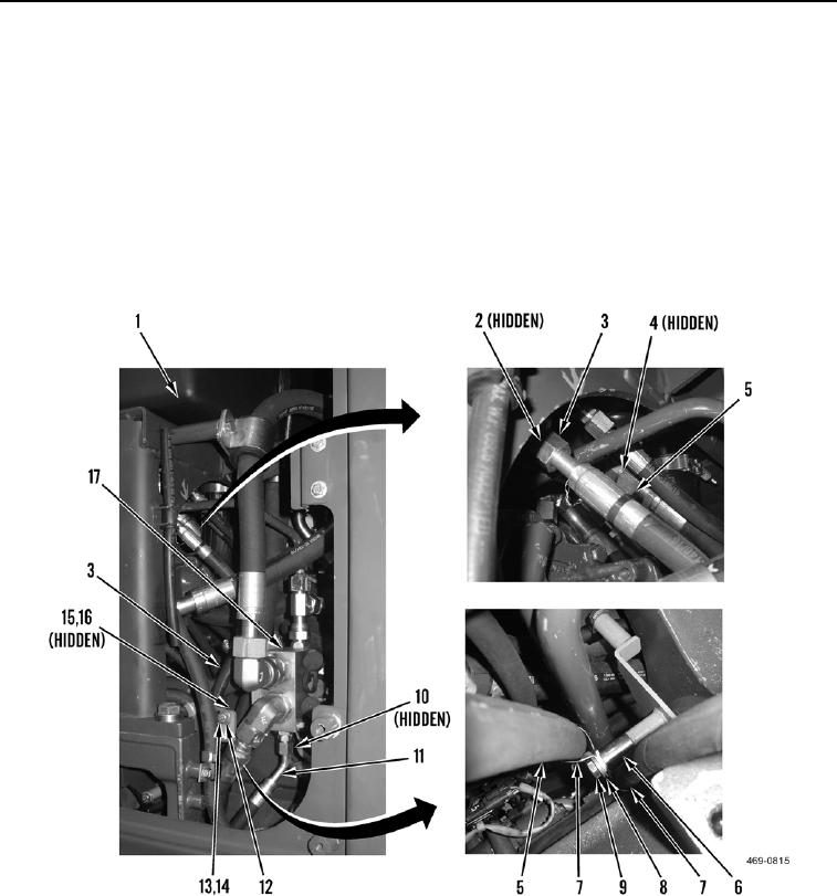
INSTALLATION CONTINUED
6. Install new O-ring (Figure 8, Item 4) and secondary steering pump supply hose (Figure 8, Item 5) on hydraulic
tank (Figure 8, Item 1).
7. Install new O-ring (Figure 8, Item 2) and pressure relief valve return hose (Figure 8, Item 3) on hydraulic tank
(Figure 8, Item 1).
8. Install new O-ring (Figure 8, Item 10) and secondary steering pump hose (Figure 8, Item 11) on implement
manifold (Figure 8, Item 17).
9. Install spacer (Figure 8, Item 6), two clamps (Figure 8, Item 7), washer (Figure 8, Item 8), and bolt (Figure 8,
Item 9) on secondary steering pump supply hose (Figure 8, Item 5).
10. Install two clamps (Figure 8, Item 12), washer (Figure 8, Item 14), bolt (Figure 8, Item 13), washer (Figure 8,
Item 15) and nut (Figure 8, Item 16) on pressure relief valve return hose (Figure 8, Item 3).
Figure 8. Control and Pressure Relief Valve Connections.
0175

