
TM 5-3805-293-23-4
0175
INSTALLATION
000175
N OT E
Install secondary steering pump hoses as tagged and marked during removal.
Install elbow and tee as noted during removal.
Route secondary steering pump hoses as noted during removal.
1. Install new O-ring (Figure 6, Item 7) and tee (Figure 6, Item 3) on pressure relief valve (Figure 6, Item 6).
2. Install new O-ring (Figure 6, Item 5) and elbow (Figure 6, Item 4) on pressure relief valve (Figure 6, Item 6).
3. Install three new O-rings (Figure 6, Item 2) and secondary steering pump hoses (Figure 6, Item 1) on pressure
relief valve (Figure 6, Item 6).
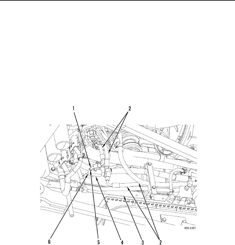
4. Route four secondary steering pump hoses (Figure 7, Item 2) to machine.
5. Install spacers (Figure 7, Item 6), pressure relief valve (Figure 7, Item 4), two washers (Figure 7, Item 5), and
bolts (Figure 7, Item 1) on rear frame (Figure 7, Item 3).
Figure 7. Pressure Relief Valve.
0175

