
TM 5-3805-293-23-4
0169
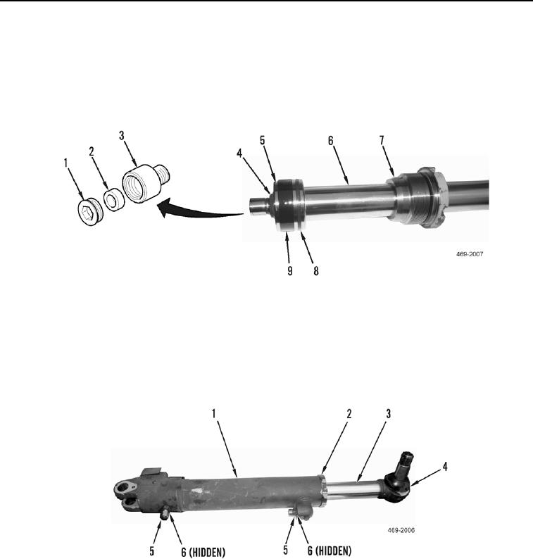
ASSEMBLY CONTINUED
2. Install head (Figure 10, Item 7), piston (Figure 10, Item 5) and new locknut (Figure 10, Item 4) on cylinder rod
(Figure 10, Item 6). Torque locknut to 443 15 lb-ft (1971 Nm).
3. Install new seal (Figure 10, Item 8) and new wear ring (Figure 10, Item 9) on piston (Figure 10, Item 5).
4. Install carrier (Figure 10, Item 3), magnet (Figure 10, Item 2) and retaining ring (Figure 10, Item 1) on cylinder
rod (Figure 10, Item 6). Torque to 26 4 lb-ft (116 Nm).
Figure 10. Head, Piston, and Magnet.
0169
5. Install cylinder rod (Figure 11, Item 3) in cylinder housing (Figure 11, Item 1) and tighten head (Figure 11,
Item 2).
6. Install boot (Figure 11, Item 4) on cylinder rod (Figure 11, Item 3).
7. Install two new O-rings (Figure 11, Item 6) and fittings (Figure 11, Item 5) on cylinder housing (Figure 11,
Item 1).
Figure 11. Cylinder Rod.
0169
END OF TASK

