
TM 5-3805-293-23-3
0167
INSTALLATION CONTINUED
000167
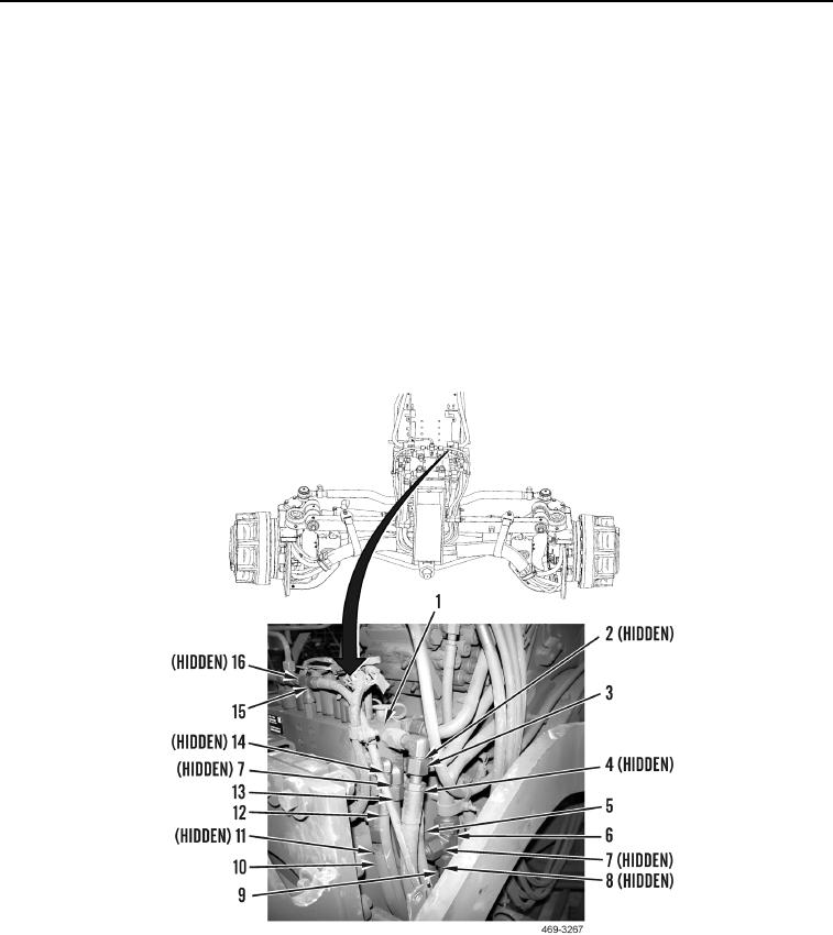
34. Install new O-ring (Figure 25, Item 16) and connect hose (Figure 25, Item 15) to AWD manifold (Figure 25,
Item 1).
35. Install new O-ring (Figure 25, Item 11) and connect hose (Figure 25, Item 10) to AWD manifold (Figure 25,
Item 1).
36. Install two new O-rings (Figure 25, Item 7) and connect tube (Figure 25, Item 13) to AWD manifold (Figure 25,
Item 1 and tee (Figure 25, Item 6).
37. Install new O-ring (Figure 25, Item 14) and connect hose (Figure 25, Item 12) to AWD manifold (Figure 25,
Item 1).
38. Install new O-ring (Figure 25, Item 8) and connect hose (Figure 25, Item 9) to tee (Figure 25, Item 6).
39. Install new O-ring (Figure 25, Item 4) and connect hose (Figure 25, Item 5) to AWD manifold (Figure 25,
Item 1).
40. Install new O-ring (Figure 25, Item 2) and connect hose (Figure 25, Item 3) to AWD manifold (Figure 25,
Item 1).
Figure 25. Left AWD Control Manifold.
0167