TM 5-3805-293-23-3
0167
INSTALLATION CONTINUED
000167
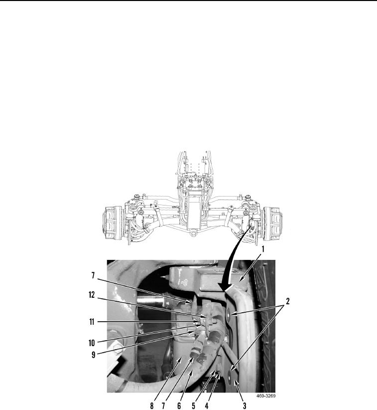
24. Install two clamps (Figure 22, Item 9), bolt (Figure 22, Item 11), two washers (Figure 22, Item 10) and nut
(Figure 22, Item 12) on wiring harness (Figure 22, Item 7) and hose (Figure 22, Item 6).
N OT E
Install wires as tagged during removal.
25. Connect wiring harness (Figure 22, Item 9) to wheel spindle (Figure 22, Item 1).
26. Install guard (Figure 22, Item 3) and two machine screws (Figure 22, Item 2) on wheel spindle (Figure 22,
Item 1). Torque to 75 lb-ft (8.5 Nm).
27. Install guard (Figure 22, Item 8), two washers (Figure 22, Item 4) and bolts (Figure 22, Item 5) on wheel spindle
(Figure 22, Item 1).
Figure 22. Left AWD Motor Guards.
0167

