
TM 5-3805-293-23-3
0142
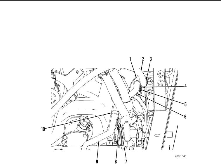
INSTALLATION CONTINUED
58. Position transmission oil tube (Figure 76, Item 9) on machine.
59. Install hydraulic fan control manifold outlet line clamp (Figure 76, Item 3), transmission oil tube clamp
(Figure 76, Item 1), washer (Figure 76, Item 4), and bolt (Figure 76, Item 5) on transmission oil tube (Figure 8,
Item 6) and hydraulic fan control manifold outlet line (Figure 8, Item 2).
60. Install clamp (Figure 76, Item 9), washer (Figure 76, Item 8), bolt (Figure 76, Item 7), and transmission oil tube
(Figure 76, Item 6) to machine.
Figure 76. Transmission Oil Tube Clamp.
0142