
TM 5-3805-293-23-3
0138
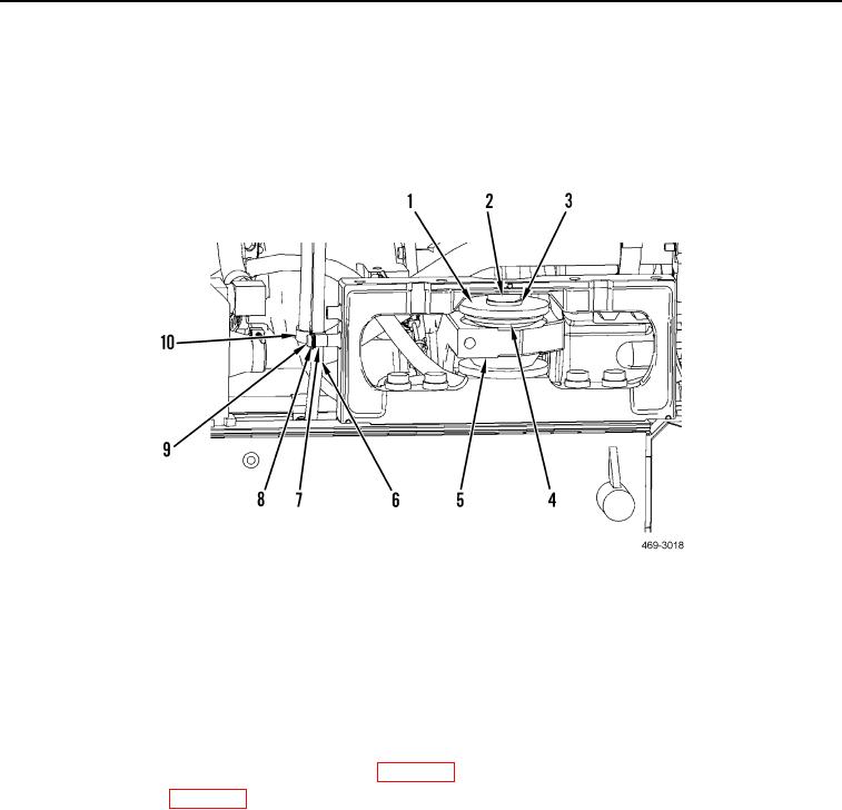
INSTALLATION CONTINUED
9. Install two clamps (Figure 6, Item 10), spacer (Figure 6, Item 7), washer (Figure 6, Item 8), and bolt (Figure 6,
Item 9) on hydraulic hoses (Figure 6, Item 6).
10. Install resilient mount (Figure 6, Item 4), washer (Figure 6, Item 3), washer (Figure 6, Item 1), and bolt
(Figure 6, Item 2) on right side transmission mount support (Figure 6, Item 5). Torque bolt (Figure 6, Item 2) to
1,096 lb-ft (1,486 Nm).
Figure 6. Right-Side Transmission Mount.
0138
END OF TASK
FOLLOW-ON TASKS
000138
N OT E
Do not install hydraulic system service pack until AWD pump has been installed.
1. Install implement and steering pump assembly (WP 0120).
2. Install AWD pump (WP 0116).
END OF TASK
END OF WORK PACKAGE