
TM 5-3805-293-23-3
0138
CLEANING AND INSPECTION
000138
Clean and inspect all parts IAW Mechanical General Maintenance (WP 0346).
END OF TASK
INSTALLATION
000138
1. Install sleeve (Figure 4, Item 1), resilient mount (Figure 4, Item 2), and washer (Figure 4, Item 3) on left-side
transmission mount support (Figure 4, Item 7).
2. Position left-side transmission mount support bracket (Figure 4, Item 4) on machine. Install four washers
(Figure 4, Item 5) and bolts (Figure 4, Item 6) on left-side transmission mount support bracket (Figure 4,
Item 4). Torque bolts to 320 lb-ft (434 Nm)
3. Install sleeve (Figure 3, Item 1), resilient mount (Figure 3, Item 2), and washer (Figure 3, Item 3) on right-side
transmission mount support (Figure 3, Item 7).
4. Position right-side transmission mount support bracket (Figure 3, Item 4) on machine. Install four washers
(Figure 3, Item 5) and bolts (Figure 3, Item 6) on right-side transmission mount support bracket. Torque bolts
to 320 lb-ft (434 Nm)
5. Lower transmission and remove lifting device.
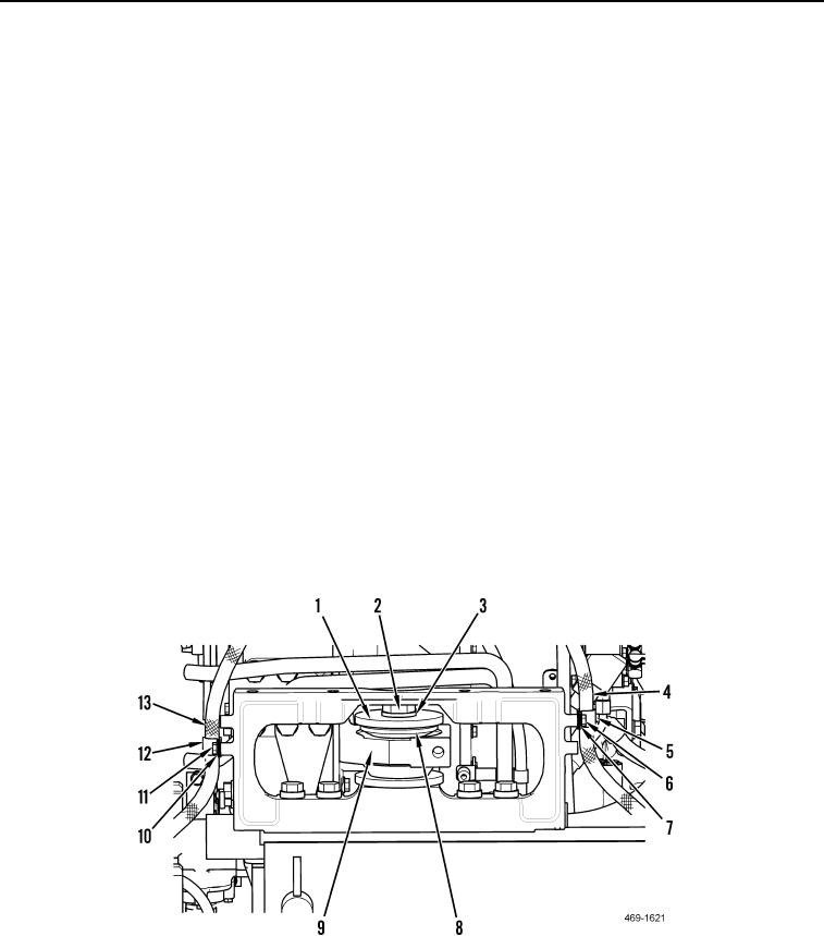
6. Install clamp (Figure 5, Item 12), washer (Figure 5, Item 10), and bolt (Figure 5, Item 11) on wiring harness
(Figure 5, Item 13).
7. Install clamp (Figure 5, Item 5), washer (Figure 5, Item 7), and bolt (Figure 5, Item 6) on hydraulic hose
(Figure 5, Item 4).
8. Install resilient mount (Figure 5, Item 8), washer (Figure 5, Item 1), washer (Figure 5, Item 3), and bolt
(Figure 5, Item 2) on left-side transmission mount support (Figure 5, Item 9). Torque bolt (Figure 5, Item 2) to
1,096 lb-ft (1,486 Nm).
Figure 5. Left-Side Transmission Mount.
0138