
TM 5-3805-293-23-3
0124
SHIM INSTALLATION
000124
N OT E
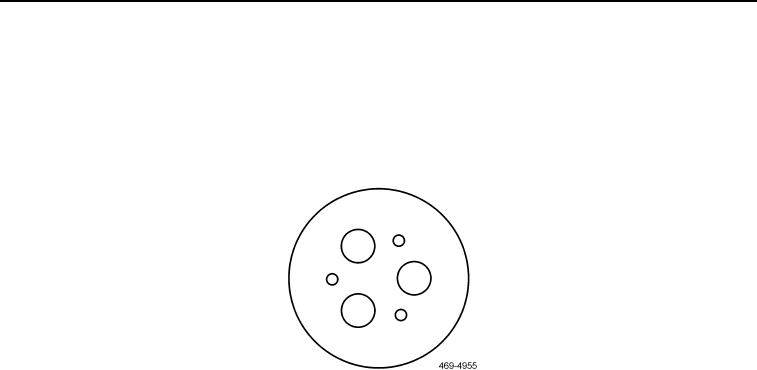
Image can be used as a template for hole locations on retainer.
1. Drill three 0.252 in. (6.40 mm) equally spaced holes on a circle with a diameter of 2.16 in. (55.0 mm) on
retainer.
Figure 10. Retainer Hole Spacing
0124
N OT E
Check rotation of final drive while tightening bolts to ensure bearing is not becoming
bound.
2. Install retainer (Figure 11, Item 2) and three bolts (Figure 11, Item 4) on sprocket (Figure 11, Item 1). Torque to
35 2 lb-ft (48 3 Nm).
3. Rotate sprockets (Figure 11, Item 1) three times.
4. Measure distance from face of spindle shaft to top face of retainer through three drilled holes and record aver-
age.
5. Remove three bolts (Figure 11, Item 4) and retainer (Figure 11, Item 2) from sprocket (Figure 11, Item 1).
6. Measure thickness of retainer (Figure 11, Item 2).
7. Install a number of shims (Figure 11, Item 3) equal to the average distance minus 0.0071 in. (0.18 mm) and
retainer thickness. Shims can have a tolerance of 0.00000.0020 in. (0.00000.0050 mm) on sprocket
(Figure 11, Item 1).