
TM 5-3805-293-23-3
0074
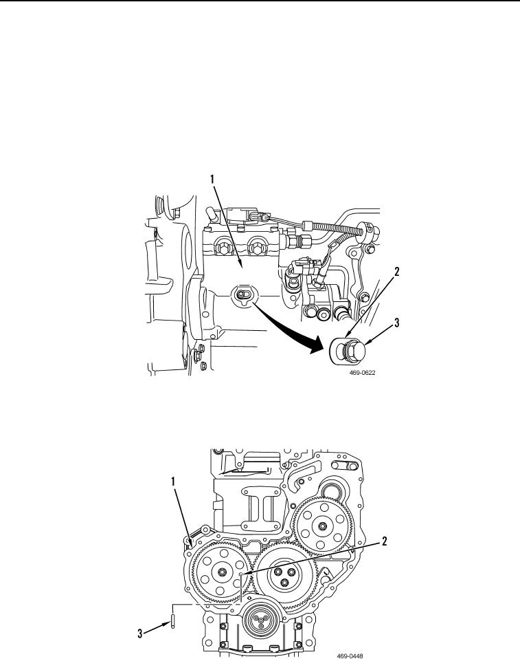
INSTALLATION CONTINUED
7. Loosen locking screw (Figure 12, Item 3) on fuel injection pump (Figure 12, Item 1).
N OT E
The locking tab has two different diameter holes. The wider hole allows the locking screw
to go deeper in the pump bore to lock the pump shaft. The narrow portion keeps the
locking screw off the pump shaft, allowing it to rotate freely.
8. Slide locking tab (Figure 12, Item 2) to unlock position.
9. Torque locking screw (Figure 12, Item 3) to 80 lb-in. (9 Nm).
Figure 12. Fuel Injection Pump Shaft Lock.
0074
10. Remove camshaft timing pin (Figure 13, Item 3) from front housing (Figure 13, Item 1) and camshaft gear
(Figure 13, Item 2).
Figure 13. Camshaft Timing Pin.
0074