
TM 5-3805-293-23-3
0069
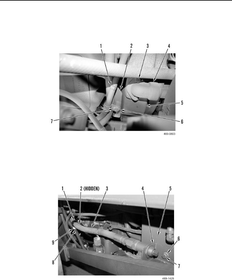
INSTALLATION CONTINUED
10. Install elbow (Figure 38, Item 4) and two bolts (Figure 38, Item 3) on flywheel housing (Figure 38, Item 5).
11. Install two clips (Figure 38, Item 1), washer (Figure 38, Item 7), and bolt (Figure 38, Item 6) on bracket
(Figure 38, Item 2).
Figure 38. Hydraulic Lines at Flywheel Housing.
0069
12. Install oil drain hose assembly bracket (Figure 39, Item 4), two bolts (Figure 39, Item 7), and washers
(Figure 39, Item 6) on transmission (Figure 39, Item 5).
13. Install two clips (Figure 39, Item 1), bolt (Figure 39, Item 9), two washers (Figure 39, Item 8), and nut
(Figure 39, Item 2) on oil drain hose (Figure 39, Item 3).
Figure 39. Oil Drain Hose.
0069