
TM 5-3805-293-23-3
0066
INSTALLATION
00066
N OT E
Install all cables and wires as tagged and marked during removal.
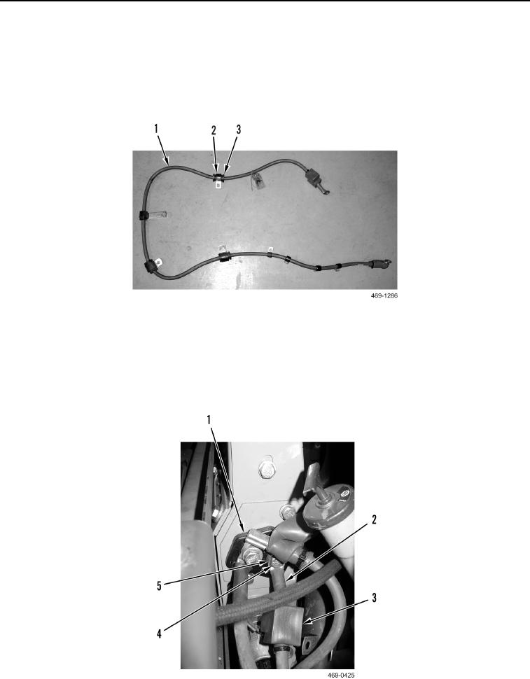
1. Install four grommets (Figure 8, Item 3) and eight clamps (Figure 8, Item 2) on positive alternator cable
(Figure 8, Item 1).
Figure 8. Cable.
0066
2. Route positive alternator cable (Figure 9, Item 2) on machine.
3. Install positive alternator cable (Figure 9, Item 2),washer (Figure 9, Item 5) and bolt (Figure 9, Item 4) on
terminal block (Figure 9, Item 1).
4. Position boot (Figure 9, Item 3) on bolt (Figure 9, Item 4).
Figure 9. Positive Alternator Cable.
0066