
TM 5-3805-293-23-3
0057
INSTALLATION CONTINUED
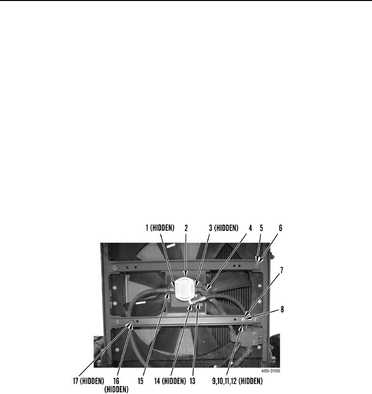
5. With assistance, install cooling fan and fan gear motor assembly (Figure 10, Item 2) on machine.
6. Install four washers (Figure 10, Item 5) and bolts (Figure 10, Item 6) on fan and fan gear motor assembly
(Figure 10, Item 2).
N OT E
Connect hoses as noted during removal.
7. Install new O-ring (Figure 10, Item 1) and connect hose (Figure 10, Item 15) to cooling fan and fan gear motor
assembly (Figure 10, Item 2).
8. Install hose clamp (Figure 10, Item 17) and bolt (Figure 10, Item 16) on cooling fan gear motor assembly
(Figure 10, Item 2).
9. Install new O-ring (Figure 10, Item 3) and connect hose (Figure 10, Item 4) to cooling fan and fan gear motor
assembly (Figure 10, Item 2).
10. Install new O-ring (Figure 10, Item 14) and connect hose (Figure 10, Item 13) to cooling fan and fan gear motor
assembly (Figure 10, Item 2).
11. Install spacer (Figure 10, Item 9), hose clamp (Figure 10, Item 10), washer (Figure 10, Item 11), bolt
(Figure 10, Item 12), washer (Figure 10, Item 7), and nut (Figure 10, Item 8) on cooling fan and gear motor
assembly (Figure 10, Item 2).
Figure 10. Fan and Gear Motor Assembly.
0057