
TM 5-3805-293-23-3
0054
INSTALLATION CONTINUED
N OT E
Hold coolant drain valve while installing nut.
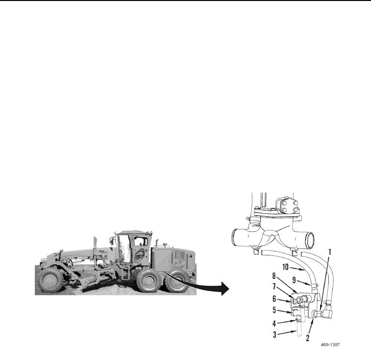
3. Install bracket (Figure 11, Item 8), two washers (Figure 11, Item 7), and bolts (Figure 11, Item 6) on machine.
4. Install two coolant drain valves (Figure 11, Item 5) and nuts (Figure 11, Item 2) on bracket (Figure 11, Item 8).
N OT E
Hold coolant drain valve while installing fitting.
5. Install two coolant hose fittings (Figure 11, Item 1) on coolant drain valves (Figure 11, Item 5).
6. Connect two coolant hoses (Figure 11, Item 10) to fittings (Figure 11, Item 1) and install clamps (Figure 11,
Item 9) on coolant drain valves (Figure 11, Item 5).
7. Connect two coolant drain hoses (Figure 11, Item 3) and install clamps (Figure 11, Item 4) on coolant drain
valves (Figure 11, Item 5).
Figure 11. Coolant Drain Valves.
0054