TM 5-3805-293-23-3
0049
ASSEMBLY CONTINUED
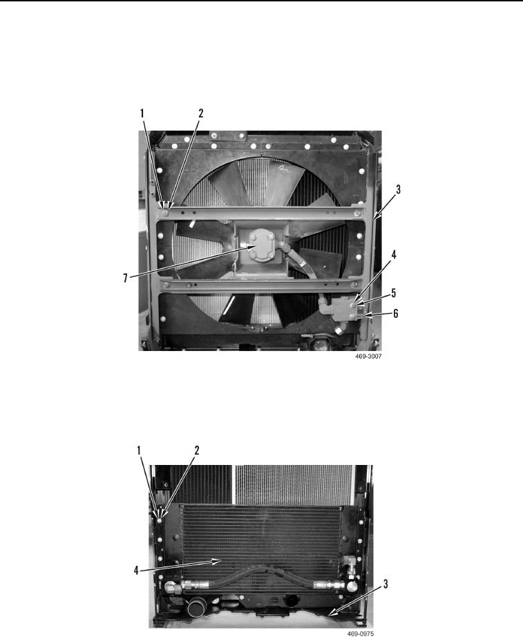
21. Install cooling fan assembly (Figure 38, Item 7), four washers (Figure 38, Item 2), and bolts (Figure 38, Item 1)
on cooling module (Figure 38, Item 3).
22. Install clip (Figure 38, Item 6), two washers (Figure 38, Item 4), and bolts (Figure 38, Item 5) to cooling module
(Figure 38, Item 3).
Figure 38. Cooling Fan Assembly.
0049
23. Install hydraulic oil cooler core (Figure 39, Item 4), eight washers (Figure 39, Item 2), and bolts (Figure 39,
Item 1) on cooling module (Figure 39, Item 3).
Figure 39. Hydraulic Oil Cooler.
0049

