
TM 5-3805-293-23-3
0044
ADJUSTMENT FOR SIGNAL NETWORK CONTINUED
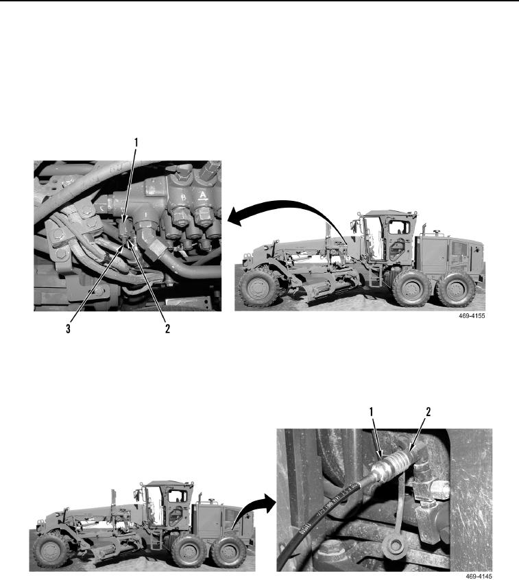
21. If pressure reading is incorrect, loosen locknut (Figure 111, Item 2) on adjustment screw (Figure 111, Item 3).
Turn adjustment screw (Figure 111, Item 3) clockwise in order to increase setting. Turn adjustment screw
(Figure 111, Item 3) counterclockwise in order to decrease setting.
22. Repeat steps 16 through 21 to adjust pressure setting correctly.
23. Tighten locknut (Figure 111, Item 2) while holding adjustment screw (Figure 111, Item 3) of relief valve signal
(Figure 111, Item 1).
Figure 111. Signal Adjustments.
0044
24. Remove hose and gauge assembly (Figure 112, Item 1) from test port (Figure 112, Item 2).
Figure 112. Test Hose and Low Side Port.
0044