
TM 5-3805-293-23-3
0044
ADJUSTMENT FOR SIGNAL NETWORK CONTINUED
00044
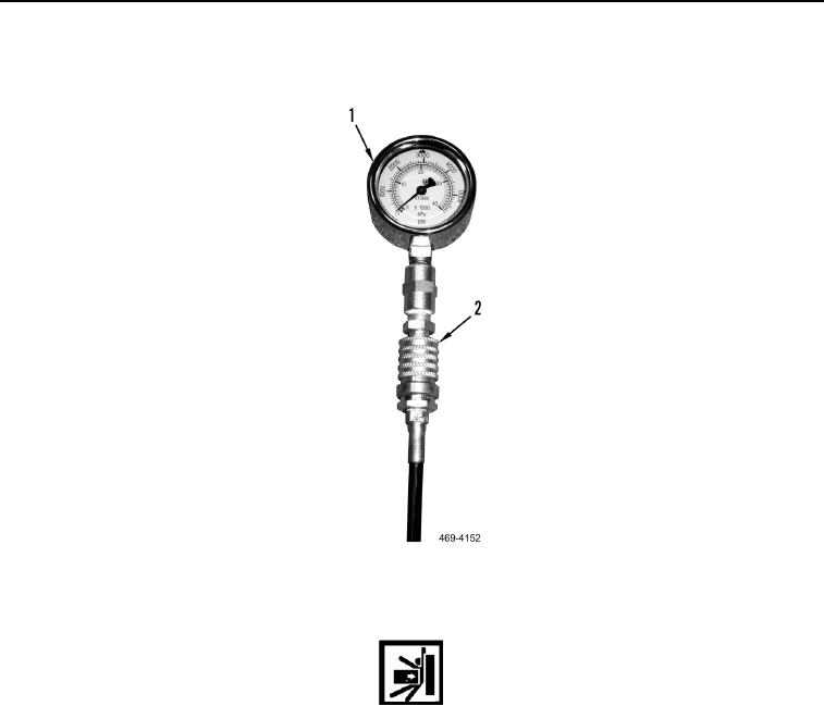
9. Connect two hoses (Figure 106, Item 2) to two pressure gauge assemblies (Figure 106, Item 1).
Figure 106. Pressure Gauge Assembly and Hose.
0044
WARN I N G
Check area around the machine before shifting the blade. Ensure the machine is clear of
personnel and obstacles. Failure to follow this warning may result in injury or death to
personnel.
10. Operate engine at wide open throttle (TM 5-3805-293-10).
11. Shift blade to full extension (TM 5-3805-293-10).
12. Stall the cylinder while observing gauge (Figure 106, Item 1). The gauge should be 3,481 73 psi (24,000
500 kPa).
13. Stop engine (TM 5-3805-293-10).