
TM 5-3805-293-23-2
0034
CAN DATA LINK CIRCUIT TEST CONTINUED
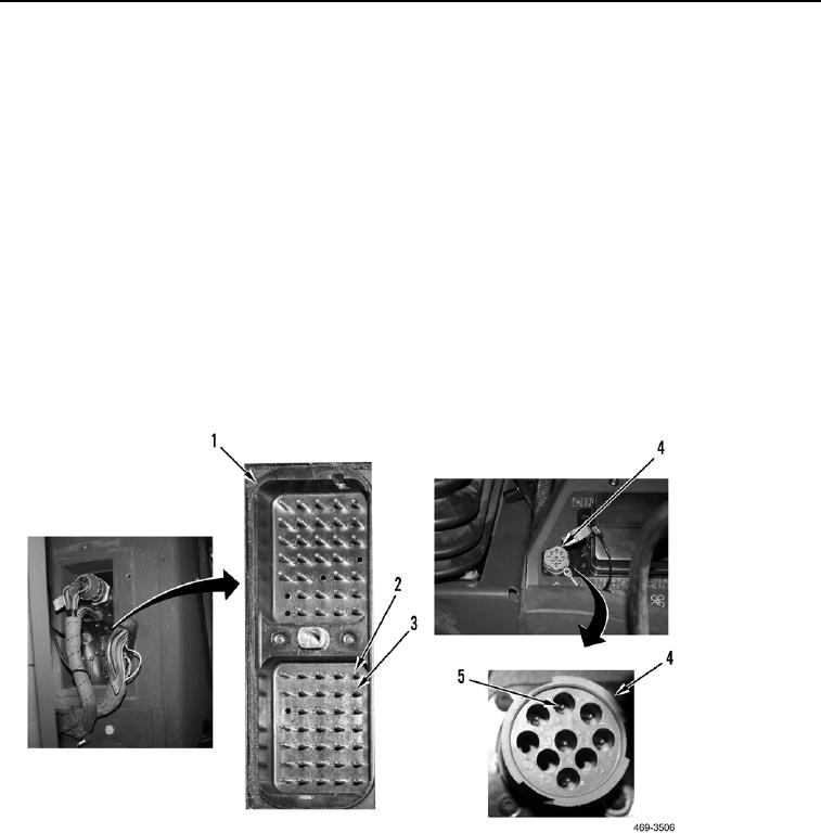
24. Using digital multimeter, test continuity of CAN- circuit K990-GN between diagnostic connector (Figure 17,
Item 4) terminal F (Figure 17, Item 5) and harness connector P-C69 (Figure 17, Item 1) terminal 8 (Figure 17,
Item 2). Resistance should be less than 5 ohms.
a. Continuity - proceed to step 25.
b. No Continuity - harness is open, replace lower cab harness (WP 0266).
N OT E
Do not measure between harness connector P-C69 terminal 8 (Figure 17, Item 2) and
terminal 9 Figure 17, Item 3) during this test.
25. Using digital multimeter, test continuity of CAN- circuit K990-GN between harness connector P-C69 (Figure 17,
Item 1) terminal 8 (Figure 17, Item 2) and all other terminals of harness connector P-C69 (Figure 17, Item 1)
and between harness connector P-C69 (Figure 17, Item 1) terminal 8 (Figure 17, Item 2) and ground. There
should be no continuity.
a. Continuity - harness is shorted, replace harness (WP 0266).
b. No Continuity - proceed to step 26.
Figure 17. Diagnostic Connector and P-C69 Harness Connector.
0034