
TM 5-3805-293-10
0013
Table 1. Preventive Maintenance Checks and Services (PMCS)
with Lubrication Information - Continued.
LOCATION
ITEM TO
CHECK/
NOT FULLY MISSION
ITEM
MAN-
SERVICE
PROCEDURE
CAPABLE IF:
NO.
INTERVAL HOURS
29
Before
Backup Alarm a. Verify that backup alarm
Backup alarm does not
function.
and Horn
functions when transmission is
placed in R (Reverse) (WP 0005).
b. Check operation of horn (WP
Horn does not function.
N OT E
Monitor system self-diagnostic test takes approximately
10 seconds to complete.
30
Before
Monitor
a. Turn engine start switch from
Fails to enter diagnostic
System
OFF position to ON position (do not test.
Indicators and
start engine) to initialize self-
Gauges
diagnostic test.
b. Monitor the following:
1. All gauges must sweep to far Any gauge does not move.
right position, then return.
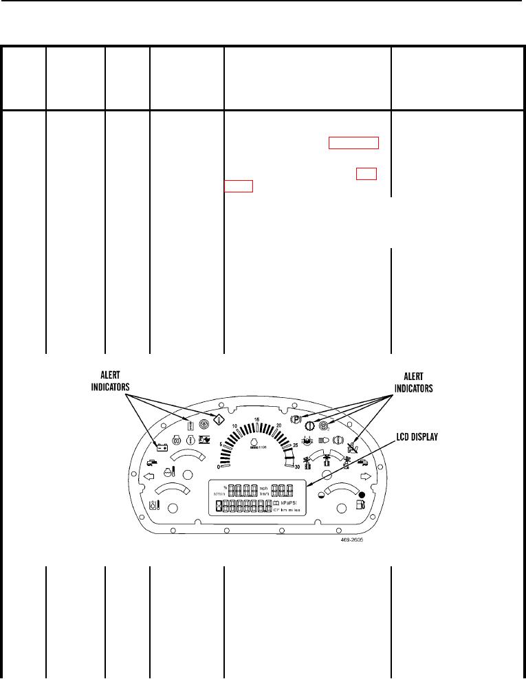
Figure 9. Monitor System Display - Gauges.
0013
2. All alert indicators must
Any alert light does not
come on momentarily.
come on.
3. All segments in LCD display LCD display segment(s)
must come on momentarily.
inoperative
4. The action alarm must
Action alarm does not
sound.
sound.
0013-15