TM 5-3805-293-10
0005
CENTERSHIFT LOCK SWITCH CONTINUED
3. To move link bar to first hole or second hole on either side of center, proceed to Step a. To move link bar to
third hole or farthest hole on either side of center, proceed to Step c.
a. Make sure that left side of blade and right side of blade are in FLOAT position. Move right joystick
centershift control in the opposite direction from what was used to position the drawbar in Step 1. As
centershift cylinder moves, linkage will roll freely. Also, link bar will move sideways.
b. Proceed to step 4.
c.
Move left side and right side of blade out of FLOAT position.
d. Simultaneously move right joystick centershift control left, and lower right side of blade by moving right joy-
stick forward. Simultaneously, raise left side of blade by moving left joystick backward.
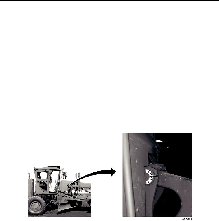
4. Line up centershift lock pin with desired hole in link bar. Use centershift indicator on right lift arm to check align-
ment.
N OT E
If centershift lock indicator light does not turn off, move link bar slightly to align hole with
centershift lock pin.
5. Move centershift lock switch to ENGAGED position (push bottom of switch). Monitoring system centershift lock
indicator light should go off when centershift lock pin is engaged.
6. Sideshift link bar toward desired direction. Use blade lift cylinders to adjust blade angle.
Figure 17. Centershift Indicator.
005
END OF TASK
0005-29

