
TM 5-3805-293-10
0005
MESSENGER DISPLAY
0005
The Messenger system provides real-time machine performance and diagnostic data with an easy-to-use inter-
face. The Messenger monitors all system data and alerts the operator to any faults through a digital text display.
The Messenger includes a Performance menu, a Totals menu, a Settings menu, and a Service menu. Each menu
has numerous options which allow the operator to adjust certain settings or monitor specific system data.
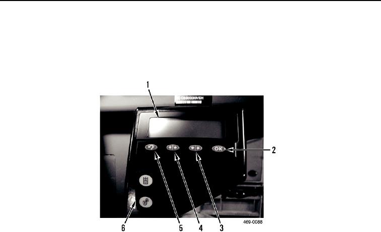
Figure 3. Messenger Display
005
1. The digital display area (Figure 3, Item 1) displays system information.
2. The OK button (Figure 3, Item 2) confirms selections after you have made them by scrolling with the Down/
Right button (Figure 3, Item 3) and the Up/Left button (Figure 3, Item 4).
3. The Down/Right button (Figure 3, Item 3) is used to scroll down and/or right through information shown on the
digital display area (Figure 3, Item 1).
4. The Up/Left button (Figure 3, Item 4) is used to scroll up and/or left through information shown on the digital
display area (Figure 3, Item 1).
5. The Back button (Figure 3, Item 5) is used to return to information previously shown on the digital display area
(Figure 3, Item 1).
6. The Implement Lockout switch (Figure 3, Item 6) locks and unlocks implement controls.
0005-7