
TM 5-3805-293-10
0005
ARTICULATION LOCK PIN INSTALLATION
0005
1. Start engine.
2. Press automatic articulation centering control on left joystick to align front and rear frames (WP 0004).
3. Shut down engine.
4. Pull back spring rod (Figure 1, Item 1) and remove articulation lock pin (Figure 1, Item 2) from storage bracket
(Figure 1, Item 3).
Figure 1. Articulation Lock Pin in Storage Bracket.
005
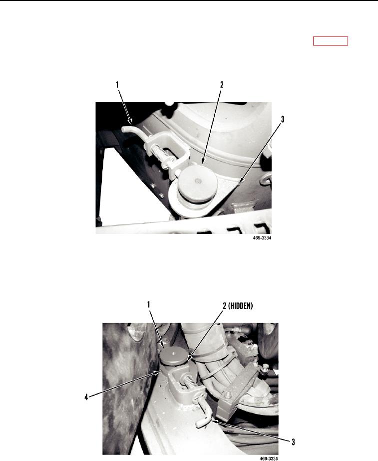
5. Insert articulation lock pin (Figure 2, Item 1) into rear frame pocket, pull back spring rod (Figure 2, Item 3) and
ensure pin lower flange (Figure 2, Item 4) contacts rear frame, then release spring rod.
6. Rotate pin until spring rod falls into detent in pin (Figure 2, Item 2).
Figure 2. Articulation Lock Pin Installed.
005
END OF TASK
0005-6