ENGINE
DISASSEMBLY AND ASSEMBLY
ASSEMBLE OIL PUMP
Tools Needed
A
B
1P529
Handle
1
1
1P461
Drive Plate
1
1P462
Drive Plate
1
1P465
Drive Plate
1
1P468
Drive Plate
1
OIL PUMP
TM 5-3805-263-14&P-2
1.
2.
3.
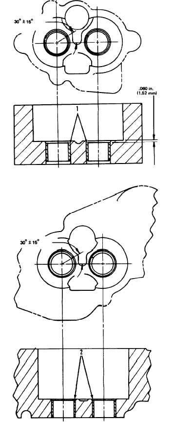
Install the bearings in the scavenge pump body
assembly with tooling (A) as follows:
a) Put bearings (1) in position on the inside of
the scavenge pump body assembly with the
chamfer on the bearing toward the outside of
the pump body. Install the bearing until it is
.060 in. (1.52 mm) below the inside
machined surface of the scavenge pump body
assembly. Make sure the joints in the bear-
ings are at an angle of 30° ± 15° from the
center line through the bores in the scavenge
pump body and toward the outlet passage of
the pump. The outlet passage has a cavity
between the bearing bores.
Install the bearings in oil pump body assembly
with tooling (A) as follows:
a) Put bearings (2) in position on the inside of
the oil pump body assembly with the chamfer
on the bearings toward the outside of the
pump body. Install the bearings until they are
even with the outside of the pump body.
Make sure the joints in the bearings are at an
angle of 30° ± 15° from the centerline
through the bearing bores and toward the
outlet passage of the pump. The outlet pas-
sage has a cavity between the bearing bores.
Check the condition of the relief valve. Check
the condition and specifications for all the parts
of the oil pump before it is assembled. See OIL
PUMP (2P1785) in SPECIFICATIONS.
1-201


