ENGINE
GOVERNOR
DISASSEMBLY AND ASSEMBLY
TM 5-3805-263-14&P-2
16.
17.
18.
19.
20.
21.
22.
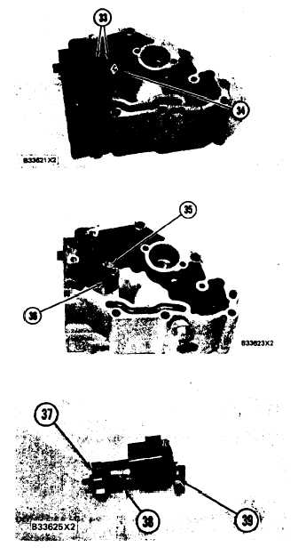
Remove bolts (33) and torque control group
(34).
Disassemble the torque control group and in-
spect the spacer, spring and insulator for dam-
age or wear.
Remove bolts (36) and block (35) for the full
load step from the housing.
Remove the bolt that holds collar (37) to bolt
(39). Remove collar (37) and spring (38) from
bolt (39). Remove bolt (39) from the block.
Remove the stop screw from collar (37) if a
replacement is necessary.
Remove bolts (41) and governor servo (40)
from the fuel injection pump.
Remove lockring (46), seat (45), spring (bro-
ken link spring) (44) and sleeve (43) from valve
(42). Remove the other lockring (46) from the
groove in the center of valve (42).
NOTE: The groove in the bottom of valve (42) must
be in alignment with the servo body to permit remov-
al from the fuel rack.
1-149


