ENGINE
DISASSEMBLY AND ASSEMBLY
TM 5-3805-263-14&P-2
GOVERNOR
ASSEMBLE GOVERNOR
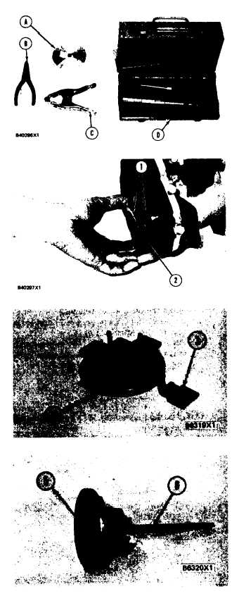
Tools Needed
A
B
C
D
6 / 2 0 5 4
Shield Driver
1
1P1555
Snap Ring Pliers
1
6V2163
Clamp Assembly
Spring Compressor
1
1P510
Driver Group
1
NOTE: If the governor was removed only to permit
repair of the fuel injection pump housing, do only
Steps 1, 4, 5, 7, 9, 10, 11, 16, 22, 37, 39, and 40.
NOTE: Put clean oil on all parts before assembly. Be
sure all oil passages are clear.
1 Install one race (I), bearing (2) and the other
race (1) on the camshaft in the fuel injection
pump housing.
2. Put flyweights (3) in position on carrier (4) and
install the dowels to hold the flyweights in
place. The flyweights must move freely on the
dowels and have 0.010 to 0.23 mm (0.0004 to
0.009 in.) end play.
3. Install dowel (5) in governor shaft (6) and in-
stall the governor shaft in the carrier as shown.
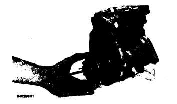
4. Put the carrier in position on the camshaft and
install the bolts that hold the carrier in place.
1-153


