ELECTRICAL TROUBLESHOOTING
TM 5-3805-263-14&P-3
INDIVIDUAL CIRCUIT DESCRIPTION
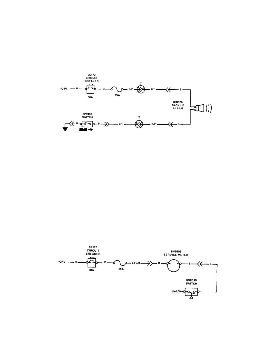
BACK-UP ALARM CIRCUIT
The back-up alarm system has a 6P8576 Alarm at the rear of the machine.
Power for the alarm is sent through the 60 amp circuit breaker, the 15 amp fuse, the
alarm, and through the 3P8990 Transmission Reverse Switch. For the backup alarm
to be activated, the transmission must be in REVERSE. The reverse switch is
activated by the transmission linkage.
Figure 3. Back-Up Alarm Circuit
SERVICE METER
Operation of the 6N5906 Service Meter is controlled by the 9G8010 Oil Pressure
Switch. When the engine is in operation, the oil pressure switch contacts close and
make a ground for the service meter. Power for the service meter is through the 60
amp circuit breaker and a 10 amp fuse.
This meter has a solid state (no moving parts) timing circuit which sends a timing
pulse (current for a short time) every 36 seconds to the solenoid that moves the
counter. When the machine is started and the meter first gets current, it takes a
minute or more for the first movement of the counter. The meter works on a 24 volt
negative ground system only.
If the meter does not work, first make sure that the red wire has +24 volts and
that the black wire is at ground. Most meter failures are really failures of the engine
oil pressure switch, or the wiring to the meter.
Figure 4. Service Meter Circuit
4-50


