TM 5-3805-263-14&P-3
DISASSEMBLY AND ASSEMBLY
HYDRAULIC PUMP
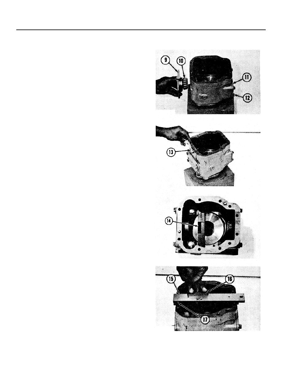
7. Heat bearing cones (10) to a maximum
temperature of 275F (135C). Install the bearing
cones on covers (9) and (11).
8. Install the O-ring seal on cover (11). Put cover
(11) in position in the pump body and the
swashplate with .015 in. (0.38 mm) shims. Tighten
bolts (12) that hold cover (11) to the pump body to
a torque of 32 lb. ft. (43 Nm).
9. Install cover (9) in the pump body and the
swashplate. Install the bolts that hold it. Tighten
the bolts evenly in 10 Ib. in. (1.1 Nm) steps until
the bolts have a torque of 40 lb. in. (4.5 Nm).
Tighten the bolts in a clockwise direction while the
swashplate is moved backward and forward.
10. Measure gap between cover (9) and pump body
with feeler gauge (13) at the four bolt locations.
Install shims that are the same thickness as the
average gap measured plus .008 in. (0.20 mm).
NOTE: If the thickness of shims is less than .005 in.
(0.13 mm) or more than .025 in. (0.64 mm), add the
thickness of the shims for cover (9) to the thickness of
the shims for the other cover. Divide the total thickness
of the shims evenly and install the same thickness of
shims on each cover.
11. Install the shims and the O-ring seal on cover (9).
Install the cover on the pump body. Tighten the
bolts that hold the cover to a torque of 32 Ib. ft. (43
Nm). Make sure the swashplate is free to move.
12. Install stop angle bar (14) from tooling (D) on the
swashplate.
NOTE: The stop angle bar must be installed with the
deepest point of the two angles toward the minimum stop
bolt. The bar must be at a 90 angle to a line through the
center of the bearings.
13. Put gauging bar (15) from tooling (D) on the body
with the end of the gauging bar against dowel (17).
NOTE: The gauging bar must be parallel with a line
through the center of the bearings.
14. Install depth gauge (16) from tooling (D) in one of
the holes in the gauging bar that is directly over the
deepest angle on the stop angle bar.
3-246


