TM 5-3805-263-14&P-3
VEHICLE SYSTEMS
HYDRAULIC PUMP
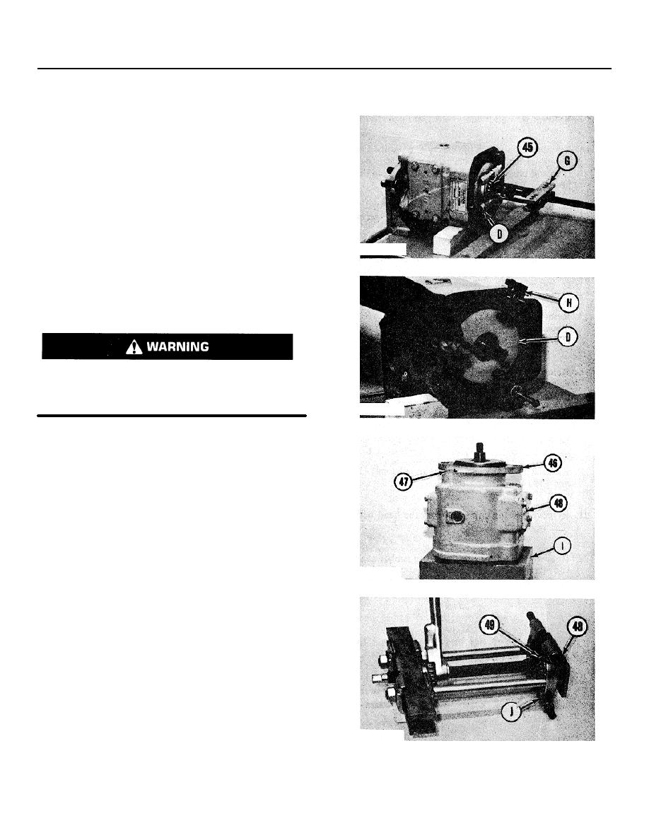
23. Put tool (D) in position on the face of the barrel as
shown.
NOTE: Tool (D) must be used to prevent damage to the
highly finished face of the barrel.
24. Install tooling (G) as shown on bearing (45).
25. Remove the bearing from the shaft with tooling
(G). Remove tooling (G).
26. Put tooling (H) in position on the pump body as
shown.
Tighten the nut on tooling (H) to put
compression on the spring in the barrel.
27. Remove the spiral snap ring from the shaft with
pliers as shown. Remove tooling (H).
Do not remove the second snap ring. The snap ring
holds a large spring in the center of the barrel which
is under compression. Sudden release of the spring
can cause personal injury or pump damage.
28. Put tool (I) in position on the shaft. Remove the
bolts that hold the pump to tool (A). Hold tool (I) and tilt
the pump until it is in a vertical position on tool (I).
29. Remove the bolts and the washers that hold
covers (48) to pump body (46).
30. Remove covers (48) from the body. Remove the
O-ring seal and the shims from each cover. Put
identification on bolts (47) as to their location in the body.
Remove bolts (47), the washers and the shims. Remove
the O-ring seals from the bolts.
31. Install tooling (J) on the covers.
32. Remove bearings (49) from covers (48) with
tooling (J).
33. Remove tooling (J).
3-241


