TM 5-3805-263-14&P-3
Remove the cap screws securing the base plate. Tap
with soft mallet to break the gasket seal. Scrape off any
gasket material from crankcase and plate.
CONNECTING ROD ASSEMBLIES
(NOTE: Before removing the connecting rods, mark
each connecting rod and its cap. Each connecting
rod is matched to its own cap for proper bearing fit,
and these parts must not be interchanged.)
Straighten the prongs of the connecting rod bolt
lock strap and remove the bolts and bearing caps.
Push the piston with the connecting rods attached
out the top of the cylinders of the crankcase.
Replace the bearing caps on their respective
connecting rods. Remove the piston rings from the
pistons. If the pistons are to be removed from the
connecting rods, remove the plugs and press the
wrist pins from the pistons and connecting rods.
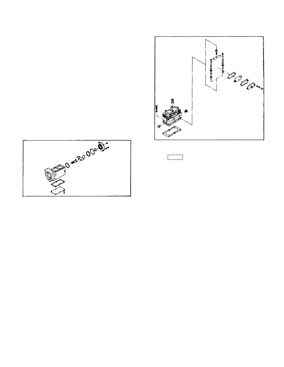
FIGURE 7 CYLINDER BLOCK EXPLODED VIEW
BLOCK (Fig. 7)
Remove the air strainer.
Remove cap screws securing cylinder block to
crankcase; separate crankcase and cylinder block and
scrape off gasket.
Remove unloader spring, spring saddle and spring seat
from cylinder block.
FIGURE 6 -CRANKCASE
Remove end cover, remove end cover seal.
Remove unloader guides and plungers and with the use
of shop air blow unloader pistons out of cylinder block
Remove the crankshaft from the crankcase. The
unloader piston bores.
compressor has a sleeve-type bearing In the end cover.
If the clearance between crankshaft journal and bearing
Remove inlet valve guides; inlet valve seats can be
exceeds .0065 in. the sleeve bearing should be replaced.
removed but only if they are worn or damaged and are
being replaced. Unloader bore bushings should be
inspected but not removed unless they are damaged.
3-136


