TM 5-3805-263-14&P-3
AIR SYSTEM AND BRAKES
4.
Stop the engine, but do not turn the disconnect
switch off.
5.
While looking at the test gauge(s), push the brake
pedal down rapidly several times to release
pressure air.
6.
The electric buzzer and the indicator light for low air
pressure must operate at 60 + 6 psi (415 + 40 kPa).
7.
If the buzzer and/or light does not operate, or does
not operate at the correct pressure, turn the
disconnect switch off and check the electrical
connections for the buzzer, the light and the
pressure indicator(s). Check the bulb for the
indicator light.
8.
If necessary, connect a continuity light across the
terminals of the pressure indicator(s).
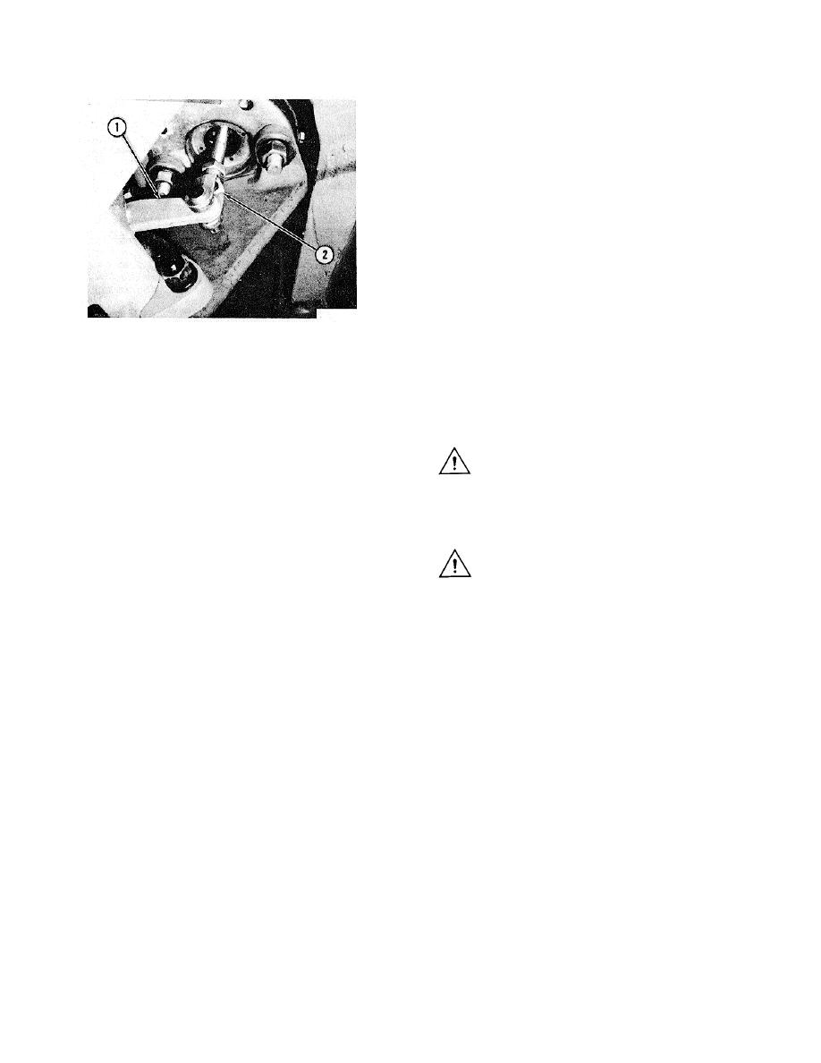
ROTOCHAMBER FOR PARKING BRAKE
NOTE: The pressure must be below the specifications of
1. Lever. 2. Rod end.
the indicator.
Checking Electric Warning Systems
9.
If the continuity light does not operate, install a new
Stoplights
indicator.
1. Make sure all of the pressure air is released from
10. On machines with the two section air tank, check
the air tank.
the other indicator.
2. Push the brake pedal down fully.
3. Start the engine and look at the test gauge.
WARNING: Before disconnecting the test
gauge(s) and hose assemblies, make sure all of
NOTE: Look at the test gauge for the right section of the
the pressure air is released from the air tank.
air tank.
4. The stoplights must operate when the pressure is
CONTROL VALVE FOR
approximately 5 psi (35 kPa).
SERVICE BRAKES
5. Release the brake pedal.
WARNING: A change in braking characteristics
6. If the stoplights do not operate or do not operate at
or a low pressure warning may be an indication
the correct pressure, stop the engine and check the
of a failure in one of the brake circuits. The
stoplight bulbs, the electrical connections for the
machine should not be operated until repairs
stoplight switch on the brake control valve.
have been made and all circuits have been
7. If necessary, install a new stoplight switch.
checked. Always check the brakes after brake
repair before the machine is put back into use.
Pressure Indicator(s) for Low Air Pressure
1. Start the engine.
Every 300 service hours, clean around the pedal,
2. The electrical buzzer and the indicator light for low
plunger boot and mounting plate. Lubricate the pedal
air pressure will operate until the pressure is above
roller, roller pin and hinge pin. Inspect the plunger boot
approximately 65 psi (450 kPa).
(1) and replace if damaged. Check the mounting plate
3. Let the pressure go up to approximately 100 psi
and pedal for correct installation and alignment.
(690 kPa).
Lubricate the plunger (2) with 5P960 Multipurpose-type
grease.
Every 2000 service hours inspect the inlet and
exhaust valves (5) and (7), O-ring seals, rubber spring
(3) and all other parts. Replace the parts that show wear
or damage.
3-129


