TM 5-3805-263-14&P-3
Use two 8M2885 Pressure Gauges [O to 200 psi (O to
TESTING AND ADJUSTING
1380 kPa)] to check the delivery pressure for the service
brakes on both sides of the machine. Connect the
Push the brake pedal to several positions between fully
gauges to the delivery ports (4) and
released and fully applied. Check the delivery pressure
on the test gauges to see that it varies (changes), the
same amount for both left and right brakes with
movement of the brake pedal.
Make a full application of the brakes. Release the
brakes. The reading on the test gauges should go to 0
psi (O kPa) very fast when the brakes are released.
The delivery air pressure shown on both test gauges
with both air tank pressures the same, should be within 5
psi (35 kPa). This is normal for this valve.
Leakage Check
Make and hold a full application of the brakes, 115 to
140 psi (795 to 1000 kPa). Put a mixture of soap and
water on the exhaust port (8).Permissible leakage is a 1
inch (25.0 mm) bubble in three seconds. If the leakage
is more, repair the valve and test again.
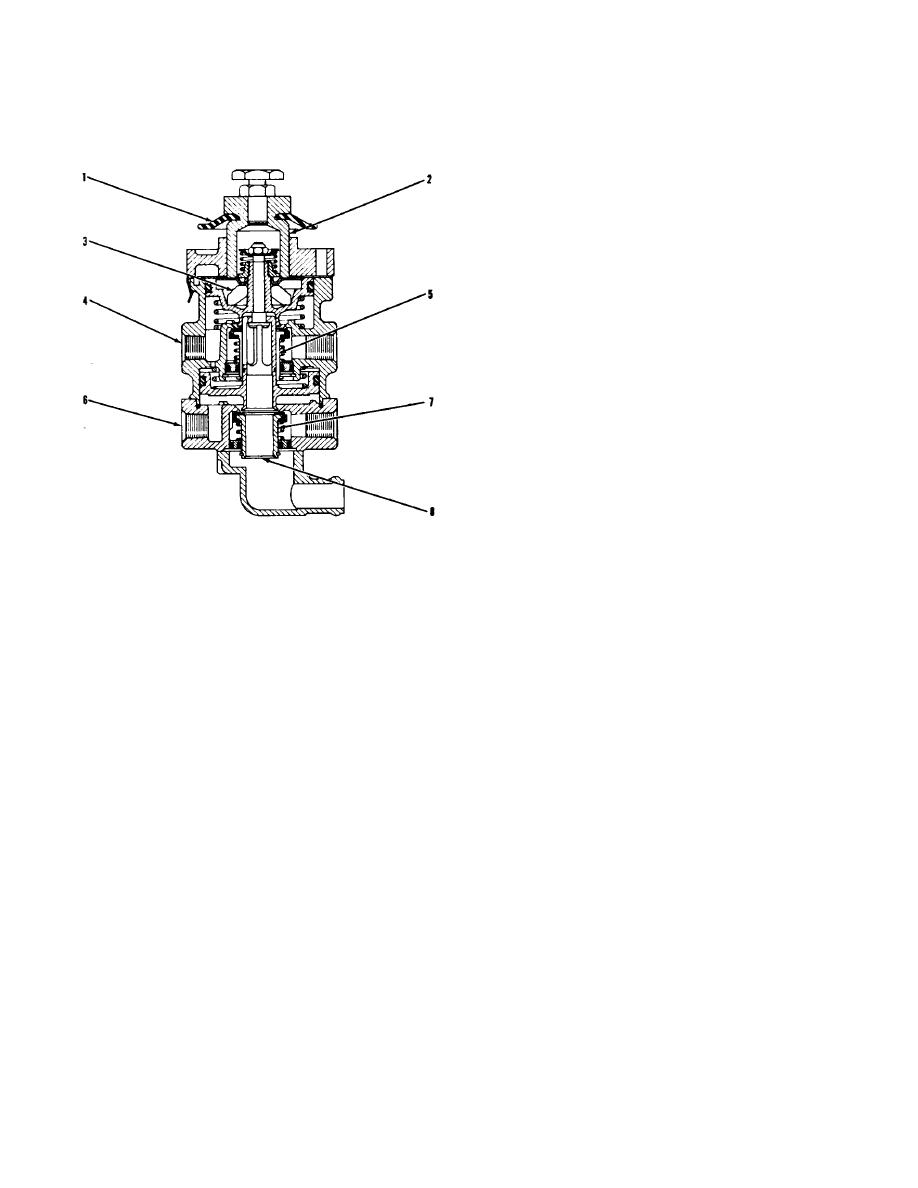
2G6680 CONTROL VALVE FOR SERVICE BRAKES
1. Plunger boot. 2. Plunger. 3. Rubber spring. 4.
Delivery port. 5. Inlet and exhaust valve. 6. Delivery
port. 7. Inlet and exhaust valve. 8. Exhaust port.
3-130


