TM 53-3805-263-14&P-3
TESTING AND ADJUSTING
CENTERSHIFT LOCK PIN
VISUAL CHECKS
Before making any operation checks to the air system
and brakes, visually inspect the complete system as
follows:
1. Check for cracks or wear in hoses and lines.
2. Check for restriction to flow; like sharp bends, clamps
that are not installed correctly and damage to hoses
and lines.
3. Check for loose connections.
4. Check for damage to components.
OPERATION CHECKS
Operation Checks of the air system and brakes can be
used to find the source of leakage in the system or to
make a diagnosis of bad performance.
CENTERSHIFT LOCK PIN
NOTE: Before making any operation checks, be sure the
LOCK POSITION
drain valve is opened to release any water in the air tank.
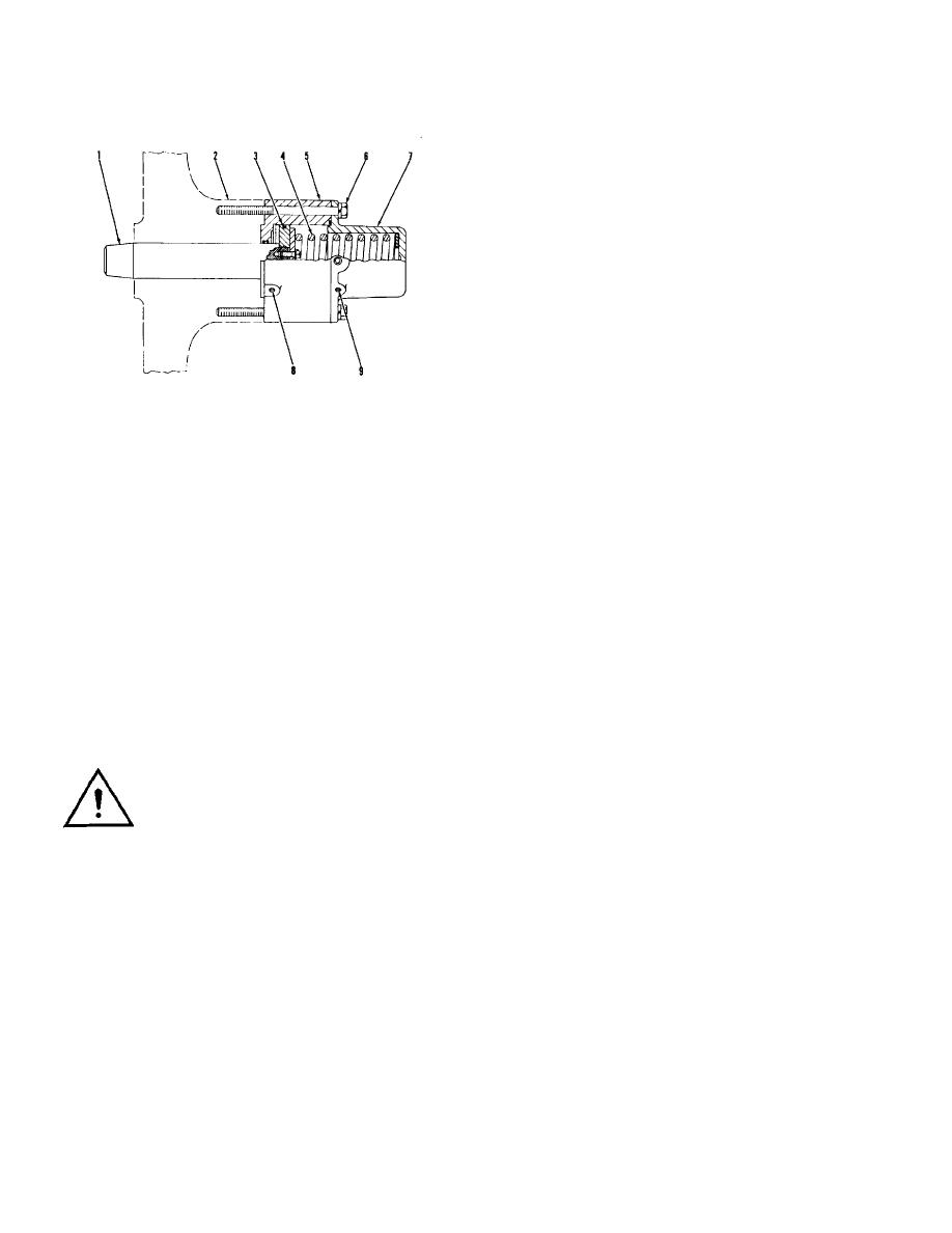
1. Lock pin. 2. Link bar. 3. Piston. 4. Spring. 5.
Water causes a reduction in the volume of air in the tank.
Housing for piston. 6. Bolts. 7. Housing for spring. 8.
During normal operation of the machine, this reduction
Port to lock pin side of piston. 9. Port to spring side of
can cause the air compressor to run constantly. Close
piston.
the drain valves.
In the LOCK position, pressure air from the centershift
Leakage Checks
control valve goes through port (9) to the spring side of
NOTE: It is possible to hear the sound of air leakage. Air
piston (3). The pressure air helps spring (4) engage lock
leakage can be seen when soapy water is put on the
pin (1) in the lock plate.
connections, valves and hoses.
1. Start the engine and let the air pressure go up to the
To push the lock pin out of the lock plate, the centershift
cutout pressure. Stop the engine.
control valve is first moved to the INDEX position. This
2. Check for leakage in the hoses and connections from
releases the pressure air in port (9) through the control
the air compressor and governor to
valve. The control valve is then moved to the RETRACT
the air tank.
position. Pressure air from the control valve is then sent
3. Check for leakage in hoses, lines, connections and
through port (8) to the lock pin side of piston (3). The
components from the air tank to the control valves.
pressure air has enough force to push the lock pin out of
4. Check for leakage in the control valves.
the lock plate against the force of spring (4).
5. Push the brake pedal for the service brakes down and
check for leakage in the signal hoses and
WARNING: Before making any checks of
connections from the brake control valve to the relay
the air system and brakes, move the
valves, the relay valves and the hoses, lines and
machine to a smooth horizontal surface.
connections to the service brakes. Release the brake
Install the safety lock pin and lower all
pedal.
implements to the ground. Make sure the safety lever is
6. Pull the safety lever to the brake OFF position and
in the PARK position. Keep all other personnel either
check for leakage in the hose and connections from
away from the machine or where they can be seen. Put
the control valve for the parking brake to the quick
blocks in front of and behind the wheels.
release valve on the rotochamber.
3-124


