TM 5-3805-263-14&P-3
AIR SYSTEM AND BRAKES
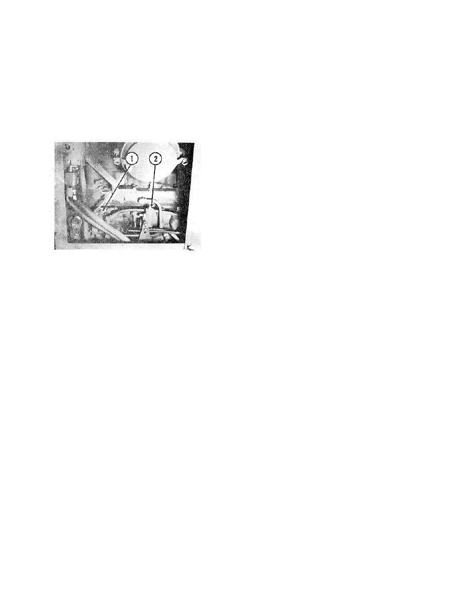
AIR COMPRESSOR AND GOVERNOR
NOTE: Because of the small amount of pedal movement
The engine operates air compressor (1) through the
and air needed to move the relay piston (12), the brakes
timing gears. The air compressor governor (2) controls
for the left side of the machine are applied almost the
the system air pressure.
same time, (almost simultaneous) as the brakes for the
The governor keeps the air pressure in the system
right side of the machine.
constant. When the engine is started, the compressor
runs until the pressure in the system is at the cutout
Left Brake Application
setting of 140 psi (970 kPa). At this setting, pressure air
When the inlet and exhaust valve (9) is moved off of its
moves the governor piston to let air go through the
seat (8), exhaust seat (14) seats on inlet and exhaust
governor to the unloading valves in the compressor.
valve (20) and closes exhaust passage (15). Inlet and
exhaust valve (20) is moved off seat (19) to let air from
supply port (17) go out delivery port (18) to the brakes for
the left side of the machine.
Releasing the Brakes
When the brake pedal is released, mechanical force is
removed from the spring seat (3), rubber spring (4) and
piston (5). Air pressure and spring force moves piston
(5) which in turn moves relay piston (12) by way of screw
(2). Seat (6) is moved away from inlet and exhaust valve
(9). Inlet and exhaust valve (9) moves into contact with
seat (8) and air pressure in the lines to the brakes for the
right side of the machine goes through the center of the
When the system air pressure is at the cut-in setting of
valve and out the exhaust port (21) and the brakes for
120 psi (930 kPa), the force of the governor spring
the right side of the machine are released. At the same
moves the governor piston to stop the flow of air to the
time, exhaust seat (14) moves away from inlet and
unloading valves. The unloading valves close and the
exhaust valve (20) and inlet and exhaust valve moves
compressor again sends pressure air to the system.
into contact with seat (19). Passage (15) is closed off to
If the governor does not operate correctly, the safety
stop air flow from supply port (17) to delivery port (18).
relief valve(s) will open at 150 psi (1030 kPa) to prevent
Air pressure in the lines to the brakes for the left side of
possible damage to the system.
the machine goes through the center of the inlet and
CONTROL VALVE FOR
brakes for the left side of the machine are released.
SERVICE BRAKES
Loss of Brakes for Left Side
Right Brake Application
Should air pressure in the circuit for the brakes on the
When the brake pedal is pushed, plunger (1) puts force
left side of the machine be lost, the circuit for the brakes
on spring seat (3), rubber spring (4) and piston (5). The
on the right side of the machine will still provide for
seat (6) seats on inlet and exhaust valve (9) and closes
brakes on the right side of the machine.
exhaust passage (7). Inlet and exhaust valve (9) is
moved off seat (8) to let pressure air from supply port
(11) go out delivery port (10) to the brakes for the right
side of the machine.
3-117


