TM 5-3805-263-14&P-3
SYSTEMS OPERATION
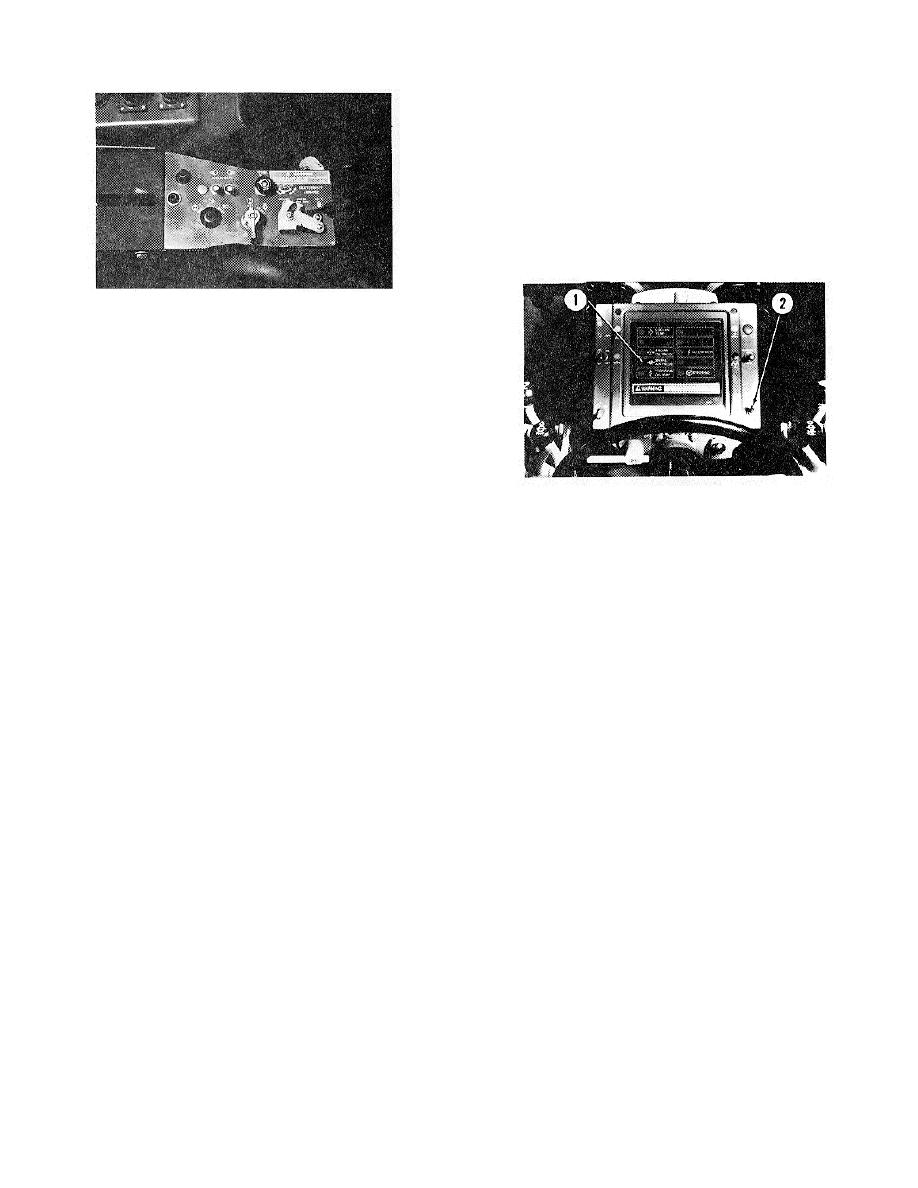
Another circuit has an indicator light (2) to show when
the differential lock is in the UNLOCK position.
The last circuit is for the brake lights. Stoplight switch
(14) and (15) are in the line from the rear section of
control valve (13) for the service brakes. When the foot
pedal is pushed, stoplight switches close.
This
completes the circuit to operate brake lights.
Each warning circuit is connected to the battery
through a separate fuse in the fuse box.
CONTROL LEVER FOR
CENTERSHIFT CONTROL VALVE
Electric Warning System
The warning system has three circuits. The main circuit
has a fault alarm and an indicator light (1) for low air
pressure. Two pressure indicators, one on each air
circuit, are connected to the fault alarm and the indicator
light. In case of a failure in either half of the air system,
one of the pressure indicators will close at approximately
60 psi (4.2 Kg/cm2). This completes a circuit to operate
the fault alarm and the indicator light. The operator can
WARNING LIGHTS
then safely stop the machine and look at air pressure
1. Indicator light for low air pressure. 2. Indicator light for
gauges (11) on the front of the engine compartment to
differential UNLOCK.
see which part of the system has the failure.
NOTE: The electric fault alarm is under the panel to the
right of the seat.
3-116


