TM 5-3805-263-14&P-3
AIR SYSTEM AND BRAKES WITH
Air from the air tank (6) goes to control valve (18). In
TWO SECTION AIR TANK
the LOCK position, air goes through the control valve to
the spring side of the piston in the lock pin housing. The
The machine is normally operated with the differential
force of the springs and the pressure air hold the lock-pi-
lock in the automatic LOCK position. To release the
i-n the LOCK position. In order to move the link bar and
differential lock, the steering panel console switch is
the circle to another location, the lever on control valve
pushed down.
(18) first must be moved to the INDEX position. This
When the panel switch is down (function indicator
releases the air from the spring side of the piston. The
light is off), a spring on the control valve holds the valve
lever is then moved to the RETRACT position. Pressure
spool in a position to let part of the oil from the No. 6
air is sent to the other side of the piston to pull the lock
clutch go to the differential lock. When the switch is
pin out of the lock plate against the force of the springs.
pushed up (function indicator light goes on) the solenoid
The centershift cylinder and the lift cylinders are then
moves the valve spool against the force of the spring to
operated to move the link bar and the circle to the
stop the flow of oil from the No. 6 clutch. With the valve
desired location.
spool in this position, a passage in the lock valve is also
opened to release the oil in the differential lock.
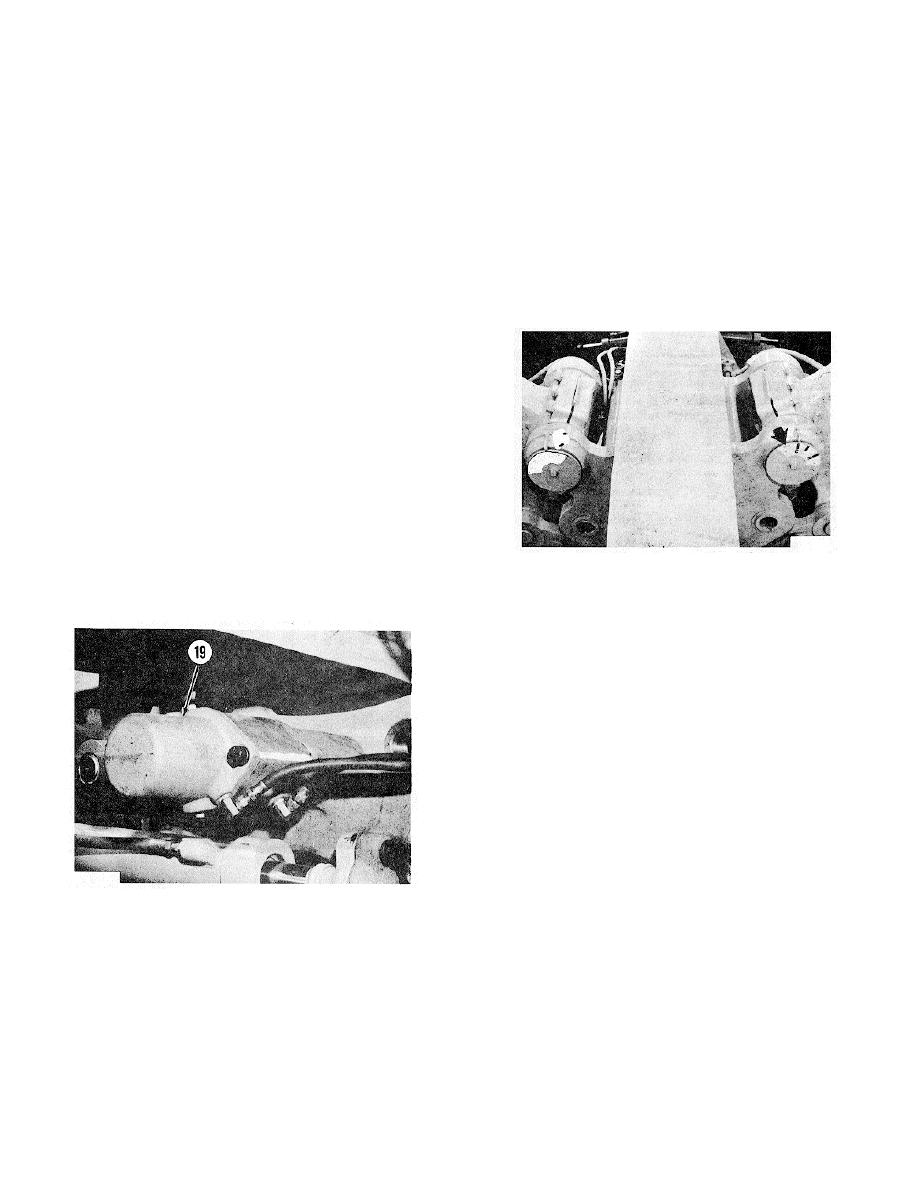
Centershift Lock
The location of centershift lock pin (19) is on the front
of the link bar. When lock pin (19) is not engaged with
the lock plate, the link bar and the circle can be moved to
put the blade in the correct position for the job
application.
Centershift control valve (18) is on the console to the
right of the seat. This control valve controls the flow of
air to the lock pin. The machine is normally operated
with the control valve in the LOCK position. Since the
CENTERSHIFT INDICATOR
lock pin cannot be seen by the operator, indicators on
pin part of the way into the lock plate. The lever on the
the rear of the lock plate show the operator when the
control valve is then moved to the LOCK position to
lock pin is in alignment with the correct hole in the lock
again send pressure air to the spring side of the piston.
plate.
The spring force and the pressure air will then fully
engage the lock pin in the lock plate.
CENTERSHIFT LOCK PIN
19. Centershift lock pin.
3-115


