TM 5-3805-263-14&P-3
HYDRAULIC SYSTEM AND STEERING
Hydraulic Pump (Cont.)
ADJUSTMENT OF SWASHPLATE BEARINGS
1.
Install shaft assembly (1) into body.
2.
Lower swashplate into body.
3.
Install O-ring to one cover assembly.
4.
Install cover on body assembly using
shim (10) with thickness of ...... 0.015 in. (0.38 mm)
5.
Tighten bolts to a torque of ...........32 lb. ft (43 Nm)
6.
Install opposite cover assembly without an O-ring,
lockwashers or shims.
7.
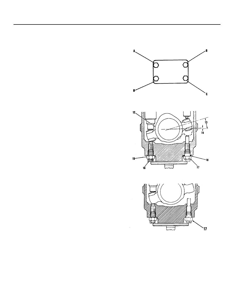
Tighten four bolts
(A), (B), (C), and (D) to .............. 40 lb. in. (4.5 Nm)
NOTE: Do not put total torque on one bolt before
tightening the other bolts. Tighten each bolt 10 lb. in.
(1.1 Nm) at a time in letter sequence. While tightening
bolts, turn the swashplate between stops.
8.
Measure the gap between the cover and swash-
plate.
9.
Use shim pack (9) with thickness equal to the
average gap plus ..................... 0.008 in. (0.20 mm)
NOTE: If the thickness of shim pack (9) is .005 to .025
in. (0.13 to 0.64 mm) do Step 10. If not, the total of shim
pack (9) and the .015 in. (0.38 mm) shim (10) used in
Step 4, must be divided equally between the two cover
assemblies.
10.
Remove the cover assembly used in Steps 6
through 9. Use an O-ring and the thickness of
shim found in Step 9 and install the cover.
11.
Tighten the bolts for the cover to .32 lb. ft. (43 Nm)
12.
After cover assemblies are installed be sure that
the swashplate will turn free between the stops
without interference from any part of the pump.
(13)
Angle for swashplate (12) to get the maximum
stroke for the pistons ..........................1600' 010'
(14)
Angle for swashplate (12) to get the minimum
stroke for pistons ................................... 020' 010'
Torque for locknut......125 20 lb. ft. (170 25 Nm)
(15)
(16)
Adjustment for maximum swashplate angle.
Torque for stop nut ....125 20 lb. ft. (170 25 Nm)
(17)
(18)
BJ1898 Shims to make the adjustment for the
minimum stroke for the pistons.
3-93


