TM 5-5805-263-14&P-3
HYDRAULIC SYSTEM
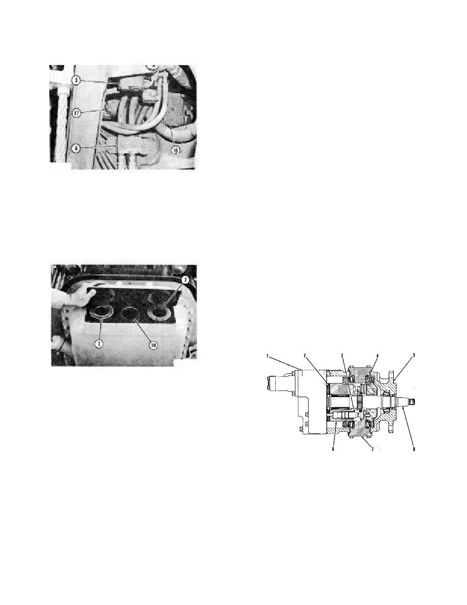
Pump (16) gets oil through a large line from tank (I). The
AND STEERING
oil from pump (16) goes through line (4) to unloading
valve (3). The unloading valve is part of the combination
valve. The pump oil in the combination valve goes to all
of the control valves in the hydraulic system.
VARIABLE DISPLACEMENT PUMP
The variable displacement pump is an axial piston pump.
The change in the output (displacement) is automatic.
The length of the stroke for the pistons is the control for
the output (displacement) of the pump. With a decrease
in the length of the stroke for the pistons, the output of
the pump is less. The movement of a swashplate in the
pump is the control for the length of the stroke for the
pistons. When the engine is stopped, a spring on a
valve in the pump keeps tle swashplate at the maximum
HYDRAULIC PUMP
angle (maximum length of the stroke for the pistons).
(Seen from left side of machine)
When the engine is running, oil at the outlet pressure of
3. Unloading valve (part of the combination
the pump is in the valve against the spring. When there
valve). 6. By-pass valve for oil cooler. 16.
is an increase in the pressure of the oil from the pump
Variable displacement pump. 17. Pump for oil
outlet, the force of the oil pressure in the valve against
to the oil cooler. The oil from the hydraulic
the spring is more and the spring gets compression
cylinders and hydraulic motor goes through filter
(shorter length). As the spring length gets shorter, the
(7), strainer (10) and into the tank.
swashplate moves toward minimum angle and the
output (displacement) of the pump is less.
The pump has two pressure settings. The load on the
hydraulic components causes the pressure setting of the
pump to change. An oil line, from the oil circuits to the
components, connects to a valve in the pump. The
pump operates at the low setting until more oil pressure
is needed for the component to move the load. When
the pressure of the oil to the component and in the line to
the valve in the pump gets an increase. the valve in the
pump
MANIFOLD FOR TANK
2. Filter (element). 7. Filter (element). 10. Strainer.
Each filter (2) and (7) has a bypass valve. If the filter
element is full of dirt, and oil can not go through the
element, the pressure of the oil gets an increase which
opens the bypass valve. The oil through the bypass
valve goes through strainer (10) and into tank (1). Each
filter has an indicator that shows when the filter element
is dirty.
Bypass valve (6) is for cooler (5). The bypass valve
VARIABLE DISPLACEMENT PUMP
opens when the pressure of the oil from pump (17) is
1. Head assembly. 2. Port plate. 3. Piston (nine). 4.
more than the pressure setting of the bypass valve. Dirt
Thrust plate. 5. Pump body. 6. Barrel assembly. 7.
in oil passages in cooler (5) will cause an increase in the
Swash-plate. 8. Drive shaft.
pressure of the oil from pump (17). The oil in the
hydraulic system can get too much heat if the oil from
pump (17) goes through the open bypass valve (6) and
not through cooler (5).
3-5


