TM 5-3805-263-14&P-3
SYSTEMS OPERATION
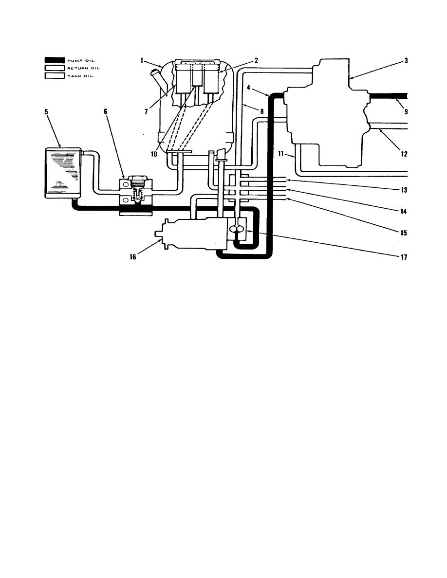
TANK, PUMP AND OIL COOLER SYSTEM (SCHEMATIC)
1. Tank for hydraulic oil. 2. Filter. 3. Unloading valve ({part of the combination valve). 4. Line from the variable
displacement pump. 5. Cooler for hydraulic oil. 6. Bypass valve for oil cooler. 7. Filter. 8. Return line from unloading
valve,. 9. Passage to the other section of the combination valve. 10. Strainer. 11. Line from the metering pump and
valve for steering. 12. Passage from pressure reduction valve and relief valve. 13. Line from the swivel. 14. Line from
the drive motor for the circle. 15. Line from the control valves. 16. Variable displacement pump. 17. Pump for oil to the
oil cooler.
The hydraulic system is a closed center system. In a
from tank (I). Lines (8, 13, 14 and 15) are for oil leakage
closed center system, the oil from the variable
from the valves in the hydraulic system. The oil leakage
displacement pump (16), has pressure at each valve in
is from high pressure oil and is a source of heat. The oil
the hydraulic system when the vehicle engine is running.
from lines (8), (13), (14) and (15) and a line from the tank
goes through a manifold and to pump (17). Pump (17)
The drive shaft for pump (16) goes through the pump to
moves this oil through oil cooler (5) and to filter (2) in
the drive shaft for pump (17).
tank (1). The oil from filter (2) goes through a manifold
and through strainer (10) and then into tank (1).
When the vehicle engine is running, both pumps are
operating. Pump (16) gets oil through a line
3-4


