TM 5-3805-261-23-2
HYDRAULIC PUMP ASSEMBLY REPAIR - CONTINUED
0330 00
ASSEMBLY - CONTINUED
15.
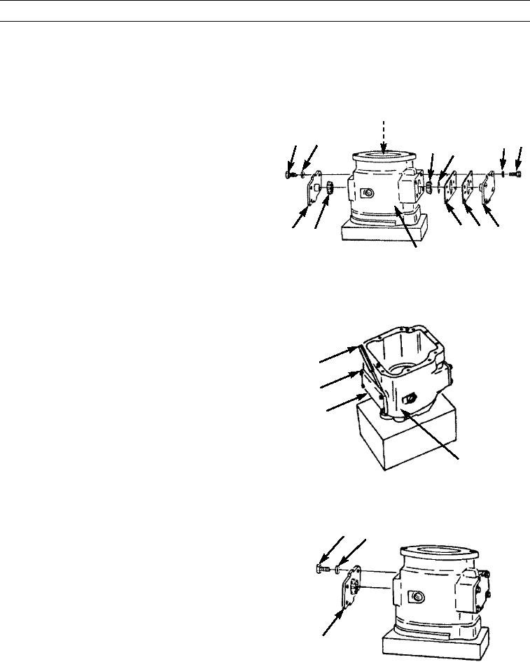
Install two bearings (103) in oil on two covers (107).
16.
Install one of two new preformed packings (104) and enough shims (105 and 106) to obtain a shim thickness of 0.015 in.
(0.38 mm) on one of two covers (107).
17.
Position one cover (107) on body (62).
120
18.
Install four of eight lockwashers (109) and bolts (108).
109
108
109 108
Tighten bolts to 32 lb-ft (43 Nm).
103 104
19.
Position second cover (107) on opposite side of body
(62) with shim(s) (105 and 106).
20.
Install remaining four of eight lockwashers (109) and
bolts (108). Tighten bolts evenly in a clockwise direc-
tion to 40 lb-in. (4.5 Nm) in steps of 10 lb-in (1.1 Nm).
Move pump housing (120) back and forth while tight-
105 106 107
107 103
ening bolts.
62
397-1515
21.
Use feeler gauge to measure gap between body (62)
and cover (107) without shims. Measure at four bolt
(108) locations. Note the average thickness and add
0.008 in (0.02 mm). This will be the total shim thick-
FEELER
GAUGE
ness to be added to cover without shims. If the thick-
ness of shims required is less than 0.005 in. (0.13 mm)
108
and more than 0.025 in. (0.64 mm), add thickness of
the shims required from feeler gauge measurement
107
plus 0.008 in. (0.02 mm) to the 0.015 in. (0.38 mm)
shim thickness of the other cover. Divide the total
thickness of the shims evenly and install the same
thickness of shims on each cover.
62
397-1516
22.
Remove four bolts (108), lockwashers (109), and
108 109
cover (107) without shims.
107
397-1517
0330 00-16

