TM 5-3805-261-23-2
HYDRAULIC PUMP ASSEMBLY REPAIR - CONTINUED
0330 00
ASSEMBLY - CONTINUED
6.
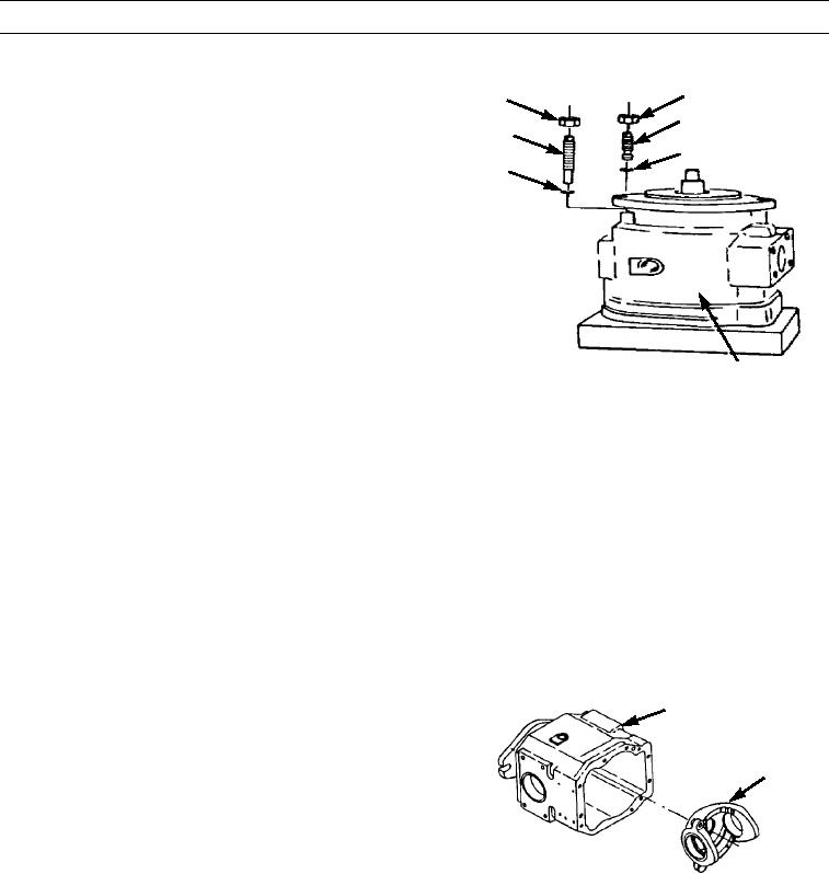
Install new preformed packing (117), bolt (118), and
110
119
nut (119) in body (62). Bolt is the maximum stop bolt
111
and must be installed in the same hole from which it
118
112
was removed. Do not tighten nut.
117
7.
Install new preformed packing (112), bolt (111), and
nut (110). Bolt is the minimum stop bolt and must be
installed in the same hole from which it was removed.
Do not tighten nut.
62
397-2505
NOTE
Perform steps 8 through 13 to adjust two stop bolts that will control pump output.
8.
Turn pump housing (62) over so that two adjustment bolts (111 and 118) are at bottom.
9.
Ensure nuts (110 and 119) are loosened and all gasket material is removed from top surface of body (62).
10.
Use depth gauge set to a dimension of 5.381 in. (13.67 cm) to adjust maximum angle stop bolt (118) until gauge is flush
with top surface of body (62) and end of stop bolt.
11.
Hold stop bolt (118) and tighten nut (119) to 125 lb-ft (169 Nm).
12.
Use depth gauge set to a dimension of 6.140 in. (15.60 cm) to adjust minimum angle stop bolt (111) until gauge is flush
with top surface of body (62) and end of stop bolt.
13.
Hold stop bolt (111) and tighten nut (110) to 125 lb-ft (169 Nm).
14.
Position pump housing (120) into body (62).
62
120
397-2218
0330 00-15

